So, after my ranting and raving about how great putting a 4agze in your ae86 was, and running through the mountains on 15psi of boost while blowing away everything else on the road…I decided the car I’d created wasn’t nasty enough, serious enough or sinister enough.
Now, most people at this point would consider me mad. Surely I’d lost my mind if 170 or so wheel horsepower in a car weighing only 1070kg wasn’t enough? After all, that’s roughly 160whp per ton, far more than the average street car, complete with rear wheel drive and an lsd. But still, after my sojourn past Corvettes and a GT40 in the mountains without so much as leaving fifth gear…I came to the realization that what I’d created was too soft. There was too much compromise. The car has a high quality stereo with several hundred watts of competition winning sound, yet I never turn it on because it would interfere with the driving experience. The car has a full interior, but never any passengers. Full steel bodywork, but it never sees traffic, much less the car shows it was built to dominate. Yes, it will pass super cars at 4000 feet but it isn’t enough.
So I’ve started over from scratch. I got myself a coupe, some friends, a large empty space and a bottomless can of time on my hands.
There is a level of Yin-Yang to this project. All of the compromises made with the first project have been addressed in the second. Where the first car was constructed to be a bit of everything, this is far more hardcore and Neutonian in its approach: The first project caused a reaction. This second project is designed to cause an equal and opposite re-action.
In my ae86 power page, I gloss over various ways of making a car go fast. From the dawn of the 1950’s hot rod up until modern day, the easiest way to make big power has always been the same: Get a bigger engine. Where the original ae86 had a 1.6L 4agze running 15psi with all kinds of bolt-ons and headwork, this one features a 2.0L sr20det turbo making even more boost. It has a JDM reflashed ECU for more power and is made out of aluminium for a lighter weight. The rest of the car follows the same trend. The brakes are 50% thicker and 20% wider. The power is up 100%. A roll cage is being planned for my safety and structural rigidity. The windows are being tossed in favour of lightweight acrylic. The steel body panels are leaving for fluffier fibre glass and carbon. The body has been widened several inches to make room for a suspension that’s nothing short of track-tastic. In short, where the other car coddled you with driveability in all weather, this one pounds your kidneys, mugs you for your wallet and asks you how you liked it.
Needless to say, this is a test of my personal mettle. I’ve often said “If I knew then what I know now, I could build this identical car for a fraction of the cost.” Call this a theoretical proof of that…me putting my money where my mouth is (and foot could be). Can it actually be done? Can someone build a car this good with $10,000? If I can, that will be roughly 1/3 what the previous car cost including body work, engine swap, 3 suspensions, several sets of wheels and tires, bumpers, guages etc. The entire ae86 experience for 1/3 the price of what was already a stellar end result. Just to keep me on the honest side, I’ll be tallying the bills as I go.
Having said that and shot my mouth off in typical “me” style, here’s where things sit so far:
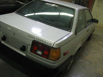
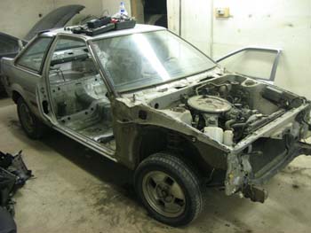
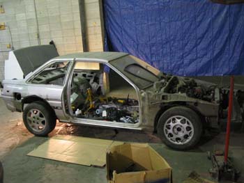
The donour car is a 1984 Toyota ae86 sr5 that I picked up on the open market for $1000. It was essentially rust free, with an automatic drivetrain and the usual nonsensical sr5 bits. The first thing I did was strip the car bare and note anything I should re-use. That left the actual chassis, so I put everything else up for sale.
I sold the interior for $100, the front suspension for $100, the front fenders for $100, headlight trim bits for $20, headlight retainer bits for $20 and the rear axle for $50. At current tally, that rings up a current starting point of $610. Not so bad.
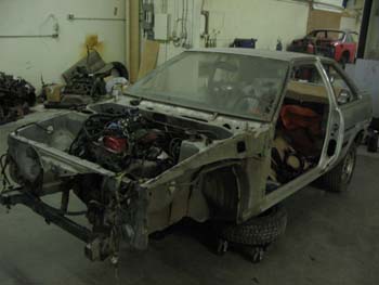
The next thing I did was get a drivetrain. I shopped around and found most sr20det engines and transmissions sell from $1600-$2400. The biggest problem with these is that they are all sitting on blocks, out of a car with no way to test them. In short, you’re taking your chances. Luckily for me, I found someone who had an sr20det in a running JDM Silvia that they didn’t want, and sold it to me for $1800 as long as I took it out myself. They even through in a few spare bits like the entire front and rear suspensions, cross members and all the other chuff I thought I’d need. That brings our total to $2410.
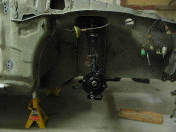
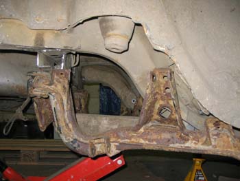
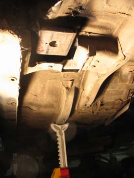
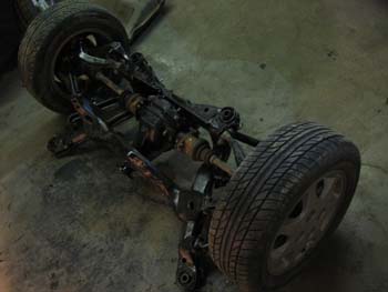
Giving the installation a lot of thought and looking at what everyone else was doing I formed a battle plan. While all the other “smart” ae86 tuners doing sr20 swaps were cutting up OEM ae86 crossmembers, making custom engine mounts etc, I went my own way as usual. Forget making parts! I test fit a few pieces, did some measurements and came to a startling conclusion: Re-using the stock S13 pieces is the easiest way to put an sr20 into an ae86. I ovalled the engine cross member holes using a drill with a carbide burr by approximately Ľ of an inch, hit each frame-rail edging with a hammer once or twice to move it another 1/8 of an inch on each side and the cross member bolted into the car using all ae86 factory hardware. I then reconditioned the s13’s front control arms, hub knuckles and steering rack using a wire wheel and two new ball joints ($140 + $120 labour for pressing) and with a loaned set of coil overs from said s13, bolted the entire s13 front suspension into the car using ae86 strut tops.
That brings us to $2670. I should mention I already had these control arms boxed by a welder friend of mine for strength.
I should drop a couple of s13 tidbits here. It seems that Nissan, while making the coolest JDM cars of the early 90’s, is also the stupidest OEM on the face of the earth. They genuinely don’t like being helpful, having discontinued almost every part of the 240sx in every year. In fact, you can’t go to Nissan and buy ball joints…they don’t exist. They want you to buy the entire front control arm. My tip is to go to NAPA and order the arms for $150 a pair, as they come complete with new joints and bushings rather than replace the joints themselves for nearly twice that money ($260). I was railroaded into doing it this expensive way, and have added it to my total as such, but it is avoidable. Ball joints from a 1995+ Sentra SE-R are the same as the s13 front…so they are available even though everyone will tell you it’ll never work and its impossible blah blah blah.
Rear ball joints are conventionally available, as are complete rear arms. The joints for the rear are cheaper ($20) than the front, but the complete arms are more than twice as much ($175 each) so I’ll leave that one up to you.
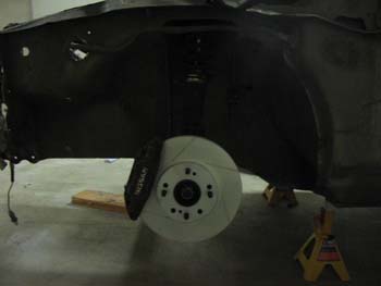
Now, because I went with the s13 front suspension, the track of the car has been widened a whole 6 inches, giving me a gigantic footprint on the road for such a small car. It also lets me easily hang upgraded brakes…like…oh…I dunno…the 4-piston aluminium mono-block
Nissan GT-R calipers I got for $125…you know…the ones that squeeze 32mm thick, 12” wide cross-drilled and slotted Powerslot rotors ($257) from PDM racing? Ones that come with pads already? That brings us to $2952. Custom brake lines will have to be fabricated.
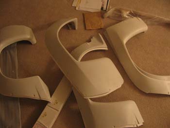
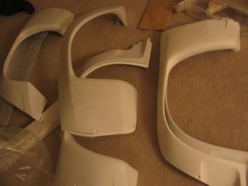
In order to cover this sudden increase in width-mad awesomeness, I’ve ordered a complete N2 bodykit from a Japanese shop called Aeromaster. That cost another $350, bringing total cost to $3202. I decided when I started the project that regardless of anything, it was going N2 for one simple reason: Cost of bodywork. It’s far cheaper to just cut off rusty rear fenders/rockers and replace it with a cosmetic fibre glass cover, and in this case the car needs the added fender to be road-legal anyway. Win win in my opinion.
I already have more than enough aftermarket wheels, spacers and everything else needed to fill the wheel wells lying around.
With my usual “don’t need it” mentality running strong, I’ve designed the new car without a power steering system. Several people have already told me this is a bad idea, but it worked just fine on the old car so I’m going for it. The s13 steering rack lines up with the OEM Toyota column leaving a gap between the two of about 3 inches. The only part that has to be fabricated is the loop. In typical, non-sensical Nissan style, the rack uses metric fittings, 14x1.5mm and 16x1.5mm respectively, to attach the metal power steering hoses. As a cost-effective solution to this dilemma, I’m going to use several hydraulic fittings known as “Versil Flare” fittings to attach a length of bent steel tubing between the two rack fittings. This will allow the fluid to flow from one side of the rack to the other without need of a reservoir or pump. Parts required are as follows:
3x8” o.d. x 30” long piece of straight steel tubing ($2)
Brennen Hydraulics pn# 7005-06-14 (metric-JIC adapter) ($4)
Brennen Hydraulics pn# 7005-06-16 (metric-JIC adapter) ($4)
Aeropuip Hydraulics pn# FC2875-6 (Versil Flare nut x 2) ($1)
Aeroquip Hydraulics pn# FF9605-6 (Versil Flare ferrule x 2) ($1)I should note that this failed miserably because I couldn’t seem to bend the metal hose well enough. Some rethinking concluded that the easiest way was to buy two Aeroquip 4739-6 hydraulic fittings ($2) and a piece of Aeroquip 2556-6 hose (2ftx$4). The 4739’s screw right onto the previously purchased Brennen fittings and push into the hose for a perfect, long life fit with superior flexibility. Total is $3222.
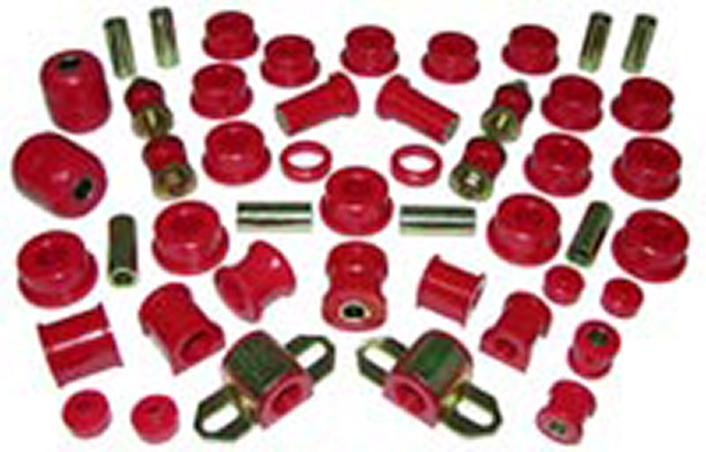
I’ve also picked up a complete Energy Suspension bushing kit for s13 from a local speed shop for $127.
This kit covers every bushing in the car, front and rear. It even comes with the replacement spacers for the steering rack. I may not use the entire kit, but considering the Toyota ae86 kit is nearly $400, the price for the Energy kit doesn’t phase me. Once the arms were reconditioned I had these bushings and the rear ball joints pushed for another $200. Total cost so far: $3549.
As near as I can tell, the only major costs left are fitting and reconditioning the rear end and subframe, making a driveshaft (if nothing OE fits that is), making a fuel system, coolant system and intercooler system…and of course, sourcing Levin front ends…
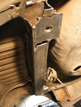
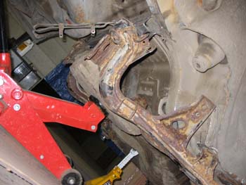
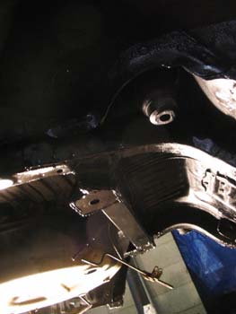
I’ve test fit the OEM s13 rear end on the car with interesting results. Once everything was aligned and aimed, it appears that the s13 suspension only requires about four inches of spacing to easily fit under the ae86. The current thought process is to take a three foot piece of 4x4 steel square tube and drill two mounting holes in it for the upper rear mounts of the sub frame. This tubing will then be welded to the bottom of the car along an OEM trunk frame cross beam that runs in front of the spare tire well and supports the panhard mount (which is no longer required). The best part is that the spare tire well can be retained, as well as the stock gas tank, lines etc, allowing for a super-cheap install. The front mounts will have to be more carefully fabricated and integrated into the car as hard pieces. From early measurements it appears that the front end mounts of the subframe will have to sit next to the front mounts of the OEM lower rear end links.
The down side to this is that this is typically a part of the car that falls to rust, and is hard to access from inside the car because it directly corresponds with the door air vent pocket. Because this entire area will be covered by the aforementioned TRD body flares, all is not lost.
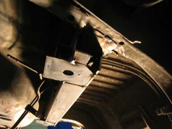
Brian, the man who did the body on my other ae86 was conscripted to help install this subframe. After a few minutes of measuring, humming and hawing, he said “yup, this shouldn’t be too hard” and set to work with a grinder. The first thing to go was the panhard rod mount. The floor of the car had to be flat, so it had to go. A piece of 3”x4” tube about three feet long was purchased and extensively chopped up to fit over the existing rear floor bracing the panhard mount was mounted to. We had to cut off one of the narrow sides from end to end and then pry the tube open slightly to “V” the shape so it would slide over the existing brace. We cut a notch into the bar in the middle so that there would be a hole to pass the fuel lines and fuel tank mounting straps through without fear of abraision. Once this was mounted on the car, Brian set to work making mounting plates to attach the subframe. The s13 has giant studs that hang off the bottom of the car that the subframe mounts to. We went in the opposite direction and created mounting plates that had nuts welded to them, allowing us to mount the frame with bolts.
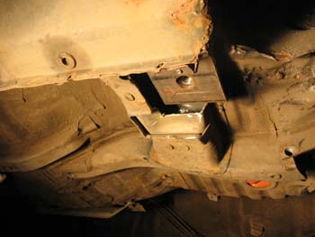
These mounting plates Brian devised in his stroke of genius are 4”x4.5” square plates that have slightly smaller plates sitting on top of them, held together by a small metal lip all the way around. This allows the small plate to move in 2 dimensions about 1/8” of an inch without fear of structural failure. A hole was then drilled through the bigger bottom plate so there was room for the bolt to
pass through the nut on the smaller plate. Once everything is tight, the small plate snugs against the bigger one’s edging, preventing motion. Simple and elegant, but effective.
Brian installed one of these plates at each end of the new cross bar, slightly off-center towards the rear. The other two were installed in the floor right where the original lower arms mounted to the car. This allows the subframe to bolt in to a structurally significant part of the car without visibility from outside. The only other modification made to the underside of the car was to notch the subframe tubes that run up the bottom of the back seat for clearance. Using an s14 subframe may prevent the need for this. While he was in there, he also welded the inner fenders to the outer fenders after I’d cut them off, essentially finishing the bodywork on the rear of the car in the process.
Now, all of this took Brian about 40 hours (give or take) for which he generously requested $500. I gave him $700 (I think…it was more anyway because $500 was just stupid). A normal shop would charge thousands. The moral of the story was measure, measure, measure and then measure again. $4249.
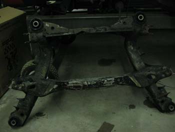
While Brian was doing all of this, I set about reconditioning the rear subframe. This was no easy task as it had been sitting under a car with no wheels in a farmer’s field for several years. Needless to say it was rusty. I had reconditioned the front crossmember with a wire wheel, but the rear was too complicated and I had to make sure I somehow got the rust out of the inside as well. Easiest way? Electrolysis. I went to Canadian Tire and got the largest kiddie pool I could find, ($20) filled it full of water until it covered the top of the subframe and dumped in a box of washing soda. I then hooked one lead from a battery charger up to it, and the other lead up to a bare piece of steel (the “sacrificial anode”) I placed in the water. Please note that there are clear instructions on how to do this type of electrolysis on the internet. Once that mixture was bubbling away, I set about cleaning and boxing the rear sub-frame arms and links. Every
two days I changed the anode for another one. It took about half an hour to be able to see the rust leaving the frame…it was actually pretty neat to watch.
After a week or so of that, the subframe was nearly bare steel…small wire wheel use fixed up the rest. I then hit it with lots of Tremclad spray paint (#2000, gloss black)…which was the same treatment the arms and links got once they were done. This Tremclad spray paint gets into all the nooks and crannies under the car and stops rust dead in its tracks. It’s specifically designed as an anti-rust coating for oilfield piping…so if it stops rust on pipes that sit in fields for years or even decades, hopefully it’ll work on the car. I sprayed the entire bottom of the car with Tremclad as well, several times over several days to make sure I got all the spots covered cleanly. Once the paint had dried, I hit it with several cans of U.S. Chemical rubberized undercoating. This is like a spray on bed liner in terms of consistency, but comes in aerosol can and thickens as it dries so you can get it into all the cracks where it will expand and seal. Needless to say the whole bottom of the car got coated with several cans of that. Lastly, all the seams and joints on the car were lined with seam sealer. Seam sealer is a specialized type of caulking designed to glue metal on cars together. Seam sealer is the thing you install body kits to bare metal with if you never want them to come off again. It comes in caulking gun form…all you have to do is squeeze it out on the seam you’re
lining and then smooth it into place with your finger. I don’t even think all the chemicals I’ve listed here cost $100, and they should keep the car alive basically forever. ~$4349.
The windows are completed. I purchased twelve linear feet of 1/8th inch acrylic plastic from a local company for $140. This was enough to do all of the windows in the car nearly twice over, but I wouldn’t recommend going with less because of the “fuck up factor”. Essentially, I removed the windows from the car, took minimum height and width measurements, and then ordered my plastic based on the height measurement alone. This left enough plastic to do four rear quarter windows, three door windows, one rear window and I still have enough left to make my gauge cluster. A couple things to note: Use acrylic and not plexiglass. Acrylic is flexible and scratch resistant.
Plexiglass is non-flexible and scratches easily. Acrylic cracks. Plexiglass shatters. Plastic shards flying around your car just doesn’t seem like a good idea.
Also, acrylic can easily be machined using common tools. I put my sheet on a carpetted floor (my living room), layed the glass I wanted to trace on top (concaved like a skateboard) and merely rolled the glass around edge to edge while tracing with a ball point pen. Make sure you leave the plastic covering on! Once the glass was traced, I went back and redid the trace with a Sharpie marker (a mid-sized one for a 1/8th inch line). Once all the windows were done I used a common grinder with a cut off disc to trim the window as close as I could get it and then sanded down the edge until the Sharpie line was gone with a flap wheel. The real trick is to take long, light sanding passes on an edge to keep it straight. You’ll have to take off more than you’d think to get it to fit, but still be careful and take your time….you can’t add material on. Never take off the plastic covering until you’re actually ready to install the window for the last (last!) time. As near as I can guess, all five acrylic windows weigh half as the rear window of the coupe by itself…maybe even less. $4500.
NOTE: Never replace the front window with anything but a regular automotive safety glass. It is made of special materials that allow the glass to stop rocks and things that will go through an acrylic window (and your face). Hence, replacing safety glass will void your insurance.
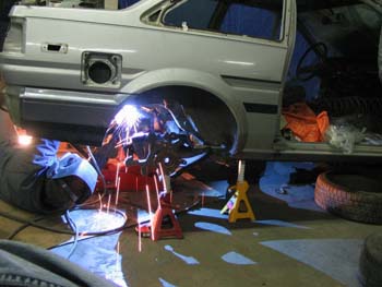
After the car was completely stripped, the car was sent out for a roll cage. Now, some of you may remember my rants against caged cars in the past and how it affected driveability…but believe me when I say this one is truly necessary. The logic here is simple…take one car, remove all of the extraneous bits you don’t need, cut up those you do, put in an engine producing nearly 3 times as much power as it was designed with from the factory and things like the body are going to break. Thus, a cage was installed to hold the car together. Currently, the car is at the fab shop getting it done, but I’ll use this down time to elaborate on exactly what has transpired so far. For starters, a professional cage builder was tapped for his expertise. I chose someone who has done numerous cars over the years, including raw fabrication of several rails (top fuel cars). After numerous consultations and research into what others have done over the years, it was decided that the best way to go was a 6 point cage…two points down the A-pillars, 2 points at the B-pillars acting as the main hoop and belt bar, and then 2 points into the trunk that X for sideways stability. The B hoop and the X bars contact the attachment points on the rear sub frame to tie that into the skeleton of the car. A halo bar, front cross bar and front suspension tie-in stubs may be added later. Chromoly was used instead of steel for its weight saving properties. All in all, the cage is expected to weigh somewhere in the neighborhood of 60lbs…or roughly as much as the glass I removed from the car. The cage is to be tied to the car’s strength points by boxing and gusseting along the way. This forces any motion at a given point on the car or cage to pull the rest of the entire car with it, greatly reducing flex in the chassis and hopefully preventing the SR20 from tearing the car to pieces.
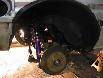
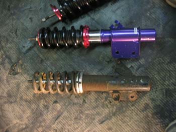
Having friends who work in the distribution industry has always made buying aftermarket parts easy. The suspension on this car is no exception. For the paltry sum of $1100, I bought a set of Tanabe Sustec Pro coilovers with chromoly sway bars for S13. These use titanium springs etc etc etc and using ae86 strut tops, bolted into the car. The only downside is that the ride heights aren’t correct, so some fabrication will be necessary. The rear sits too high by about 6 inches, and the front too low by the same. Still, for $1100 delivered, I can’t complain. That brings the total spent on the car so far to $5600.
The only piece I’ll have to add later on is a set of camber plates, though I do have a set of S13 Cusco plates I could re-use.
(for more pictures, see sr20 photo section) The cage came back to me slightly different than I had indicated above, and I need to clarify it. The 6 point cage goes from 6" square pads at the rear of the car next to the rear wheel wells through an X bar to the main hoop, were it is completely circumferencialy welded while only being about 1/2" away from the roof...you can barely get your finger over it. The main hoop loops completely from one frame rail to the other on another 6" reinforced square plate. The halo bar loops forward to just in front of the windshield across the field where the rear view mirror used to be, in front of the sunroof controls. The A pillar bars extend from the halo down to the front kick panels through the dash supports to another set of 6" plates. These bars were tied into the OEM dash cross bar, which was reinforced to handle the strain the cage may put on it, allowing me to retain all OEM dash, brake, clutch, throttle, heater and steering column features should I desire. A "wrap around" style seatbelt bar was incorporated into the main hoop. At the insistance of the builder, door bars were incorporated. He knew I intend to run the car on the street and wanted "redneck proof" the car from "beer-guided vehicles" like pickup trucks running red lights and T-boning me. The door bars were mounted low, along the OEM door sills because that way they will not intrude on the cabin's exgress or ingress and still allow me access to things like the fuel filler release, trunk release etc. Also, they will not be visible from outside the car...a real plus for dealing with the police...not that the giant X bar won't be. Lastly, gussets were installed wherever weaker points in the cage may experience pull or shift during stress moments. The A pillars were tied to the dash and kick panels, the door bars to the door sills, the halo to the side roof rails and the main hoop to the bulkheads on the sides of the car. Hopefully I won't ever have to take the cage out!
I contracted the roll cage builder to make a special adapter for the front suspension to fix my ills. Essentially, he's going to fab me a spacer block out of aluminium that pushes the front suspension mount down from the car an inch or two. This will add equal ride height to the car. It will also allow me to deflect the camber plate out more at the lower height where it will not interfere with the car's body for greater correction. The top is ae86 strut top bolt pattern while the lower end is s13 to fascilitate the use of the Cusco plates I already have. At worst, this me the chance to use complete s13 suspension kits later without fitment consequences, which is really the goal here. I do not want to build a car where every second piece of a system is off some weird make and model that I'll never remember. Another realistic consequence is that this car may go up for sale at some point, and I don't want to burden the next owner (if any) with a headache like that either. Cost of the cage and adapter plates for the suspension was $2200 including labour and materials, bringing our total to $7800
Once the car was back from the cage shop, it was time to work on the drivetrain. The body was removed from the engine/transmission, which allowed me to access the coolant lines at the rear of the motor without interference, as well as install the steering rack, line loop, column extension, the gauge senders and test fit exhaust components. I've ordered a compliment of Autometer Sport Comp gauges from JB Automotive including oil temp, oil pressure, water temp, boost/vaccuum, pyrometer, fuel pressure and AEM wideband. That cost about $650. I'm not going to add that to my total because while I've been working this project I've kept selling parts and storing the $ in Paypal knowing the gauges were needed...so essentially the car's parts paid for themselves, give or take some dollars. I will have to add in a tach and speedo once I sort out which ones will work with the SR20 system.
I've ordered fenders from a local company called Dash Distributors...they are an automotive specialty store that is an affiliate of the company I work for, which gets me brownie points and cheap prices. Both front fenders were $220 with tax. I've been told by their people that this pair of fenders is the LAST pair of fenders from Cross Canada. Cross Canada is one of the last manufacturers of body parts for these cars, so that is surely a sign of doom for future enthusiasts. I also ordered a Nissan S13 clutch slave from Dash for the paltry sum of $16. $8040.
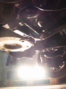
I'd like to take the opportunity to throw in some tidbits I've come across at this point. For starters, I do not believe any pounding of the firewall will actually be required. The hoses and brackets that are contacting the firewall at the moment can easily be moved out of the way and relocated using common aftermarket bits like loose hose and a Dremel. The lines in question are the coolant lines that run from the back of the engine to the heater core. At the rear of the engine, one of these hoses crosses to cool the turbo on the driver's side (JDM passenger side). There is no reason that the turbo coolant line couldn't be run as a hose and tucked under the overhang at the rear of the cylinder head. Also, there does not appear to be any interference with the transmission/bell housing and the tranny tunnel on the car itself, which is a real plus. It should be noted the transmission tunnel is the hardest, thickest and strongest metal in the car, and I was NOT looking forward to moving it around. I usually reffer to the tunnel as the "spine of the car" because everything hinges on it from end to end and it holds the entire car together. In fact, I intend to reinforce the transmission tunnel as much as possible, taking cues from OEM manufacturers like Subaru.
The other important tidbit has to do with brakes. In a moment of experimentation, I wondered out loud what master cylinder I should be going to to feed the 300zx brakes. While I am sure the OEM ae86 master will work much like the s13/s14 master's will, why chance mediocre braking power when changing a master cylinder is an effective solution? One of my friends is an s14 enthusiast and I knew he had a 300zx master lying around for future use on his own car, so I borrowed it for some comparison testing. I made some offhand comment like "wouldn't it be cool if it just bolted into the car?" as I drove away. Well, guess what? It bolted into the car. The hard lines do not line up with the ae86 lines as the 300zx master's feeds come off the side, not the top. The nice thing is, on the ae86 the master feed lines drop down into a distribution block and then feed to the rest of the car. All I have to do is make new lines from the master to the distribution block and I can utilize the onboard system to its fullest. At some point I may have to include a proportioning valve.
The last wild car is the exhaust, but it looks like that should clear. A friend lent me some Trust stuff to test fit and it looks good so far. The down pipe should clear the firewall, and even if it doesn't it will be easy to lengthen. The elbow looks like it should fit between the firewall and motor as well. The only thing left to chance that I know of is the steering column...whether or not it will hit the exhaust is something left to see. Worst case, the exhaust gets moved.
This friend and I also looked over some of the redundancies found in the SR. I noticed earlier that many of the SR20's systems seem to disappear on aftermarket tuner cars, but that doesn't mean that things are safe to toss without forethought. There are several duplicate systems such as positive crankcase ventilation that require some attention. You're always going to want *some* PCV, but having 4 seperate ones seems kind of anal. Also, there is an EGR system on the SR20 that has an exhaust outlet that goes into a vaccuum activated box which then feeds into the intake before the turbo. This is easy enough to remove and plug. There is also a PCV tube that feeds crankcase gasses into the intake charge, again before the turbo. This means that oil and other crud is going into the intake system, through the turbine, the piping, the intercooler, blow off valve, throttle body and intake manifold to get burned. Seems like a roundabout way of doing it that pushes crap through several valuable and expensive components. I think I'll be fixing that, for starters. I also note that the car has come with a manual boost controller and some kind of HKS blow off valve. The boost controller is your classic fish-tank style knob, which I've made the mistake of turning back and forth so it is no longer set properly. The blow off valve seems to be missing parts...there is no visible spring inside or moving diaphram to speak of. I may have to take it apart to find out what's up.
I plunked the steering rack in using the urethane bushings from the Energy Suspension kit over the weeked. This went in fairly easily, but was not without its share of "huh?" moments. For starters, one of the bushings in the kit only went 80% of the way around the rack! This seemed quite odd to me, but I ran with it anyway hoping that the rack mount brackets would squish it into place. Either way, the rack isn't going to be moving. The position of the rack has my attention because it looks like the column is going to go straight through the downpipe. The s13 is much wider, so the column hits the rack in that car at a much better angle, coming in from the side. The ae86 requires the column to hit the rack almost perpendicularly. This is a problem that will have to be solved later on, but I do see that as a small price to pay for the simplicity the rest of the car has come together with.
I also rebuilt the steering column over the weekend. This was something that had to be done to make the column actually reach the rack. I took the end of the steering column off a Mk III Supra because its roughly two inches longer than the stock ae86 rack. To do this, you must remove the center shaft from the column. So, never having taken apart a column before I printed off the Toyota service manual "how to's" and set to work only to find out that the "how-to" is wrong. I'm not sure if this is because the manual is for an '87 and my car's an '84, or just because they've made a mistake. You'll need a bench to work on the column after you've removed the column from the car. Take off all the plastic covers and crap that covers the column. Then remove the three screws that hold the cover over the bearing at the top of the column. Then remove the c-clip/spring clip at the top of the bearing. If you then undo the three bolts that hold the ignition key and steering lock to the column and give it a tiny pry off with a bar, the accident-colapsing section of the column with extend. This will allow you to pull back the key mount, exposing the bearing so you can pull it off. You may then undo the two bolts at the bottom of the column that hold the lower column in and you can then pull the center shaft through.
Once the center is out, you can proceed to remove the U-joint that holds the actual D-shaft to the column and then replace it with the one from the Mk III. If you take it to a "professional" to get this done, they'll tell you it can't be because the U-joint is "staked" and not conventionally available as it is too small. In short, its because they don't know any better. The trick is to gently tap the shaft at the joint in one direction with a hammer. This will remove the staking from the joint caps and push the caps out of the shaft. Be careful not to go hard or you could bend things! Also, DO NOT LET THE CAPS FALL ON THE GROUND. You *MUST* catch them as they come off the shaft. This is because the caps are full of needle bearings, which are like little metal tubes that line the inside of the cap like the fence of an old Canadian fort. Make sure as you take the caps off that these are all standing in the correct direction and put a drop of grease in the cap to prevent losing them. Then, tap the shaft in the other direction to loosen that cap minding the bearings again. At this point the shaft should be seperate from the joint. To put the longer shaft on, put it over the joint and gently tap a cap into place. Then do the second and do your best to sink the caps flush and center the shafts together at the same time. This procedure isn't hard, it just takes time and attention to detail. Lastly, you'll need to "stake" the caps with a flat bladed screw driver by putting it half on the cap and half on the shaft and hitting it fairly hard with a hammer. This folds part of the metal from the shaft over the cap, which will prevent it from coming out. You can now put the column back together.
Update: Since I rebuilt the column I've had a lot of fun trying to put the car back together. I had to get an extra pair of hands to put the drivetrain back into the car. That wasn't fun, taking two days and the help of several of my friends. Once it was going in I noticed that there were several spots where the drivetrain could and would catch on the body. While it all cleared in the end, it made it hard to install so some modifications were made. I used a hacksaw to cut the back driver's side of the cylinder head off. This might seem drastic, but it is a tab that had some minor Nissan crap bolted to it from the factory. This stopped the motor from jambing against the firewall and preventing the drivetrain from twisting, which stopped the tranny from mounting properly. Also, the exhaust elbow kept getting hung up on the bottom bolt that holds the steering column rubber slip to the car. This met the hacksaw too. Once everything was said and done there was plenty of clearance around the rear of the engine and exhaust. I should say that there is now quite a bit of space at the back.
I cut off the rear coolant cross tube with the turbo line on it and moved it under the cylinder head by using hose to join it to the stubs sticking out under the intake manifold. I used the bit of tubing that had the turbo coolant outlet on it, which allowed me to run the coolant to the turbo along the top of the tranny bell housing against the back of the engine. This should allow me room to feed the turbo AND heater core, or at least I have room to loop the lines if need be. This was the whole reason for dropping the front cross member in the first place.
Once everything was back together I could get down to the business of working on what was probably the biggest problem with this swap besides the steering: The brakes.
I have the luxury of working for an industrial distribution company that specializes in industrial hoses on top of supplying general fasteners, tools etc. for the oilfield. Because of this I have a lot of expertise to draw on when it comes to making something work, much less access to our parts and other resources at cost. For this website and parts I have bought from work have been listed at regular retail pricing, so I haven't been cheating persay. This whole scenario really came into play when it was time to make the brakes work though, because we are the western Canadian distributor for Brakequip and Aeroquip (whos parts I've mentioned earlier). So, when it came time to match the brake and clutch systems of the Z32, ae86 and S13, having our hose shop behind me made life a lot easier.
First of all, mating the 300zx master cylinder to the car required bolting it into place, setting the pedal bias properly and then mating it to the car by making some new lines to get the fluid to the distribution block. For this, the shop made a set of lines that run from the master cylinder's double flare fittings, into 90deg bends and then straight into the distribution block's double flare fittings through stainless steel braided DOT line. One line is 11" plus fittings, the other 13". This got fluid to the wheel wells. The shop then made fittings that ran from the wheel well connections to the calipers, going from female double flare through 18" of steel braided DOT line to another 90deg male double flare. The shop also made me a clutch line to run from the ae86 clutch master (double flare male 90deg again to steel braid DOT to male something fitting) that was 5ft long plus fittings.
The Parts:
5 $15 labour charges (1 per hose)
1 x 11", 1 x 13", 2 x 18", 1 x 60"
10 feet of BQP BQ303 hose
7 BQP HF34 male flare fittings
2 BQP HFMF01 female flare
1 BQP HFMM02 something fittings
10 BQP BQ16 crimp sleevesI should point out that the 90deg fittings I'd mentioned above were actually straight fittings that had been bent to 90deg. This both saved money and allowed for ease of fitment. Total cost to me for these five front lines was $145. $8185. While they were at that I came up with a plan to loop my steering rack. I took a piece of BQP T375 hose and bent it into a lightbulb shape. I then cut off as much of it as I could and ring clamped hoses between it and the fittings I had purchased all the way back at the top of this article. It made a nice loop that easily fit and cleared and cost me about $1 to do. Once everything was done and there was clear indication that the brakes may actually work, I ordered pads. I brought in Hawk HPS-N pads from JB Automotive. The fronts are 300zx pads and the rears are s13 non-abs. I went with the HPS because they were designed for autocross use and had a nice temperature range from about 0-800c, much like my beloved Project Mu Titan Kai's off my other car. The pads were $187, so we'll round it to $190 for the ring clamps and bits I've left out. Total $8375.
Because the drivetrain was in, I could also get back to fitting other bits. I re-hung the doors and installed all the seals. I test fit the Koenig Rewinds I was givenn to make sure they will clear the Z32 calipers. It looks like I may actually have to cut the "Nissan" logo off the calipers and use some 1/4" spacers or else I have 25mm spacers I can use. Whether those clear the fenders is something else entirely...though in retrospect that may be necessary to fill out the flares. We'll see. I changed the rear diff drain to a new one from Nissan because someone took the old one out with Vise Grips instead of the 3/4" square drive it so obviously uses. I got the rear sway bar mocked up...it will go in nicely because it is restricted to the rear sub frame. I need to order some end links for it because I don't have them, but it should just bolt on like nothing. The front will take some fabbing because I really don't think the Tanabe chromoly upgrades will fit in the OEM ae86 location.
I re-installed the steering column to find out that no, the extension will NOT clear the gap to the new rack. It is still short by 1"-2". I'll have to get it cut in half and sleeved/welded with some chromoly tubing. That'll fix it. It looks like the knurled end of the shaft may not be the right size for the s13 rack (too small) but that should just require a sleeve as well. It could be worse!
The other thing I've done a fair amount of is mocking the front end. Because I have to hang a GReddy-style GTR core intercooler on the front of an ae86, I have been through every possible scenario in my head as to fitment. I wasn't sure if the bumper would fit over it, much less if the headlights would go on over the piping. Then, I had assumed that the lights could remain on, but that they would have to be fixed in the "up" position to clear the piping. As I found out today, if I hang the core upside down and tilt it V-mount stle, I should only have to trim the bumper mount arms a bit to get it all to work. The piping will have to be shortened because the ae86 just isn't as fat as the s13 and some holes may have to be drilled to snake it through, but the headlight up/down ability should be retained.
This may be a critical thing as I have been re-evaluating just how much attention I want to draw with this car. The Police in my area have become increasingly ignorant of import "tuner" cars in recent years. A co-worker of mine was recently written $807 in "fix it" tickets by the local constables for various offences like "illegal exhaust" (it was stock), "illegal headlights" (he had Silver Stars), "illegal body kit" (didn't know they were?), "illegal lowering" (since when are lowering springs illegal?), "illegal tint" (factory tint) and a bunch of other things as he was leaving a church for the long drive home. Because he argued with the officer as to the legitimacy of his claims, he was forced to stand with his hands on his hood as the officer's partner tore apart his car's interior looking for drugs, asked to provide receipts for his stereo because it "looked stolen" and was followed home and pulled over twice more by two other units as harassment, one forcing him to take a breathalizer test because they "suspected him of DUI". This, coupled with my experiences last summer as to what happened when I was out driving my supercharged car has not left me optimistic as to what the streets will be like. I was out driving with my hood off because I was testing the car's cooling system (it was overheating). We were on a low-traffic road off the beaten path when we came upon a head-on collision that police were controlling traffic around. Dickhead in front of me decided that he was going to drive through the intersection regardless of what the police wanted which drew attention in my direction. The officers then left the intersection (so now nobody's directing traffic) to bark at me about my lack of a hood, one with his hand on his gun which he had unlatched. That seems kind of drastic, considering they had scolded the guy who ran the intersection by wagging their fingers at him. Besides that, the officer took a hostile tone and was using less-than appropriate language in his discussion with me. Needless to say, I'm concerned what will happen with a wide body, aerodynamic aids and an electric or candy paint job.
I had intended to make this car wild, but perhaps it is time to go ultra-reserved in colour. That will cut down on most attention. I never intended to put on a loud exhaust or anything else stupid because that's just childish. However I know that the plastic windows will be a point of contention. Also, the cage and doors will be a problem should I get pulled. Height, lights, tint, stereos etc won't be a problem...all of that will remain legitimate with tried-and-true systems being employed. I'll just have to make my case in court if it becomes an issue and remind the officer to take "gave chase" off his report because he wouldn't have been able to. :)
I've set up the gas tank to go in. I did manage to get the straps connected in the OEM locations even with the modifications to the undercarriage required to mount the rear subframe. It just took some finger-tippy movements and some time, but I managed to get the gas lines out of the way and to get a bolt through the longer strap that runs up the middle of the car started. Once I pull in the tank and hook up the hoses I can cinch up the bolt and everything should mount like it came from the factory.
I removed the rear brake calipers to have a better look at them, and in doing so noted that if I had installed the OEM s13 brake Tee found at the rear of the s13 where the ae86 has its "5th" brake line I probably could have screwed the passenger side caliper into it. Lucky for me, I do actually have the Tee off the s13. Unfortunately, I cut the lines off the rear calipers when I was taking them off the donor car so we'll never know. It looks like I will have to run one braided line off the Tee to the passenger side's rear brake and run the other side in steel tubing to the drivers caliper where it will turn into a braided line. I'm not sure if I can run a braided line along the subframe without consequence, though with labour to assemble the hose as part of the equation it may be more cost effective. I can't seem to tell if the e-brake lines will work with the ae86 e-brake lever. The lines look like they might work, but all I have to mock up with is a set that have had the ends cut off. I'll have to eye ball it, but I may have to run without an e-brake, which is a big no no with the "federales". Also, it'd be nice to have a back up plan in case the brakes fail on a mountain run.
This next tidbit is for those people out there who want to argue with my theory that Nissan rolled an ae86 into their R&D department and copied it while making it fatter. The front sway bar bolted into the car. Now, the rear bolted into the car as well, but that wasn't surprising because it is isolated to the subframe, so it technically never left the s13. The front has to go from control arm to control arm across the subframe while fastening to the frame rails. The sway bars require this mount because it acts as the pivot point for the sway bar, turning it into a giant spring and allowing it to control body roll. So, to have two cars seperated by 6 or so years in design made by two different manufacturers where this suspension part is interchangeable is unheard of. I mean, the odds that the older Toyota could take a huge aftermarket sway bar intended for a Nissan that much newer without serious modification are slim to none in anyone's mind, including my own. Two minor adjustments will be required to make the bar permanent. The metal flange running down the frame rail of the ae86 on the wheel well side will have to be trimmed very slightly to create room to allow the bar's frame mount to be tightened down the whole way as the bar is currently hitting this point. The other adjustment is that the actual mount does not have a flat bottom (way to go Nissan) so washers or a spacer will have to be used under the mount to make it level when contacting the ae86 frame. I think this is game, set and match for my theory. Oh, and Nissan...here's a free tip. The next time you copy a Toyota, how about you get it right and actually IMPROVE it instead of just making it newer and fatter!
Update: Since writing that last statement my computer fried and I lost a lot of information. Hopefully I didn't lose anything significant besides some photos of the cage installation. Either way, several things have changed since I wrote that, and I need to "get back on the horse" and bang it out. I managed to install all of the brake and clutch lines I had made with no difficulty and ordered some "Super Blue" DOT3 brake fluid to make sure I was pushing the best there was. This cost $40 for two litres, bringing total to $8405. I also got the clutch pedal mounted in the OEM position by drilling a hole through the fireway in the proper spot and feeding a bolt/washer in through one of the windshield wiper valleys. Everything went in nicely and easily. I loosened the brake booster off the firewall, which allowed me to tuck the clutch line behind it, creating a cleaner engine bay look. This will also keep the line out of danger by running it along the firewall flange. The only problem with the lines is the rear brake lines. I had the rear ones made correctly, but getting them to tee into the factory ae86 line has been a bit tough because of the rear subframe. Unfortunately, the rear subframe is nearly in contact with this line. I did manage to get the tee adapter in place, but it is so tight that I cannot tighten it from under the car. I will have to revisit this as it is the only detail to handle before bleeding.
The intercooler has found a nice home between the bumper horns, though it had to be mounted with the inlets at the top. This means that the hot air does not have as much room to rise in the cooler, possibly hurting performance. Either way, it is front mounted with no modification to the vehicle...all I have to do is make a brace to hold the cooler from the bottom to the horns. Its hard to believe an R32 GT-R core intercooler can fit in the front of an ae86, but the proof is in the pictures. This lead to a unique question: Was it possible to run intercooler piping to this intercooler without serious alteration of the car and/or the bumper mounts? Using some patience, ingenuity, masking tape and a friend, we managed to take all of the intercooler tubing that came with the s13 cooler kit and frankenstein'd it into a tubing setup that would work on the ae86 with minimal modification to the car. A dremel was used to open up the area under the headlights slightly and the tubing was altered using "Mr. Messy". We managed to get the tubing from the turbo to the cooler and the cooler to the intake by carefully eye balling the bends we had and trying multiple combinations before cutting. It involved a lot of trial, error and masking tape, but when the dust settled we had two intercooler tubes. They were then taken to Jim the cage guy to get welded up after fitment. They fit perfectly...the only downside being that they may not have enough motion due to their solid design, but I can always cut them and put silicone hose joints in them if I have to. Another option is to go full Nismo engine mounts to take flex out of the system. The only wild car left in this area is the blow off valve. The drivetrain came with an old HKS unit, but I am not sure if it works. I have been told to hook it up to a vaccuum source to test it, but I have not found one that is readily available. Vaccuum pump to the rescue, I think. It should be noted that the JDM ae86 "Zenki" front bumper will easily clear the China-core and tubing, totally hiding it from view. At least this means the car still be somewhat sleeper.
Update: I finally got the blow off valve tested and it looks like it will work, so I've contracted Jim the Cage Guy to install it into the intake side of the tubing because that was where it fit best. I've also managed to make some progress in terms of annoying bits that have hung around for a while. For example, I finished the brake lines off. This required tee-ing off the rear hard line at the back of the car using the Tee that came off the S13 at the rear and screwing it straight onto the ae86. I then screwed the two rear lines directly into it and then ran them along the subframe and into the brakes. It is worth noting that this was not a fun process, requiring the removal of the entire rear subframe to accomplish. It sounds worse than it was...I removed each main subframe bolt and replaced it with a longer one one at a time, which allowed me to lower the subframe an inch or so without removing it entirely from the car *OR* having to line it up again. I then lowered it on a jack and left it hanging...did what I had to and then jacked it back up. Be careful not to get the lines caught between the frame and the body at pinch points or you will have no brakes!
I got fluid into the steering rack through some help from the GF. We hooked a small funnel up to the fittings on the rack (1/2" clear Kuritec K010-0810 hose to be precise...2ft) and poured in ATF. When the line was full, she rolled the steering wheel from lock to lock until it emptied and we refilled while I covered the other fitting with my finger to plug it. This was done until one fitting could take no more fluid at which point we switched. We then left the joint-tube empty and screwed it onto the fittings. Unfortunately, it seems as though there is too much fluid in the rack as it jambs when going lock to lock now. Some draining of the fluid should fix this, as at this point the ATF is more for lubrication than hydraulic power assist. I should mention that it is jambing to the point that the shaft is actually spinning inside the rack U-joint. I'm sure glad we found that out before I was on the street at speed! The easy solution is to drill a hole through the rack and U-joint and stick a bolt clean through both pieces to act as a torque arm.
Further investigation has concluded a couple of things about the front suspension. For starters the way to go is with the ae86 front radius rods because they bolt into the car with no fab and can locate the front control arms with minimal modification. The s13 ones can not be retrofit as easily as the rod is too big and requires significant modification to fit. The only real modification is that one of the holes on the control arm must be moved inboard less than half an inch so that it lines up straight across the control arm. Also, the ae86 rod must be wound out as far as possible in adjustment range to fit when installing and then it will be recalibrated when being aligned. The old hole in the control arm can just be welded up. The radius rod bracket will need to have the sway bar hole cut clean of for clearance though you could probably run the ae86 front sway bar with this setup with no modification...I never checked because I have sways that came with the suspension kit I bought. Lastly, the s13 sway bar will bolt over the stock radius rod frame mount, not into the ae86 factory location as last reported, and it will require washers to space one side of its sub bracket as again, the Nissan part isn't symetrical. But it will bolt in, and that is the key part. I also wound up using a larger "fender" style washer over the bracket as a safety precaution just in case something goes wonky.
I succeeded in getting the Sparco pedals mounted, though this took some doing. I bought the Sparco "race" pedals because of their bolt through design from Garage Works here in Edmonton along with a Veloce two spoke steering wheel and carbon-look shift knob. Why? For one, the bolt through pedals aren't a safety risk. Secondly, they were cheap. The knob was cheap and didn't require any kind of fancy shift boot or attachments. Lastly, the steering wheel was cheap and basic in design. Total cost for all units delivered was $335cn ($8840), which I didn't think was all that bad. Drop Annandt a call at Garage Works if you're interested. Installing the pedals was fun...had to borrow a drill etc and in doing so I completely forgot just how hard the metal in those pedals really is. I wound up using my dremel to punch the holes out with a carbide burr and then hogged them out with the drill. Also, for whatever reason Sparco didn't include enough fasteners to actually ATTACH the product, so I wound up having to source some small machine screws and lock nuts to finish the job. I was expecting more, to be perfectly honest, which is why I had gone with Sparco in the first place!
Jim the Cage Guy is also nearly done the suspension spacers. These are aluminium blocks that measure 3" thick. They have ae86 bolt pattern in the top and s13 bolt pattern in the bottom. This piece takes up the difference in the suspension in the front from each car while retaining camber adjustment. The only downside is they weren't made quite right (prototypes never are!) so some adjustment has had to be made. Overall, they are going to be just what is needed to keep the geometry in place. Jim also punched out a locator nut for the camber plates that came with the s13 suspension as somehow I lost one. $20 ($8860) I'm considering getting him to make another because its that damn nice! I also got him to put a mounting tab on the top of the intercooler over the existing one that came on the China-core unit. This tap will point straight up off the top of the cooler, allowing it to bolt right where the OEM ae86 rad support bracket went.
I used some time off that I had to get bodyshop supplies from Canada Car Color...a sister company of the one I work at. They supplied me with Fuser 803ez seam sealer, Marhyde rust stopper, some kind of metal-to-fibreglass bonder and a paint primer/sealer all for about $150 ($9k). This will allow me to mount the flares to the car...which is my next deal. Thanks to Dpunk and Wrongway for coming through with some test fenders for me. Substantial fender mods will be required, so its nice to wreck something that has no value!
Lastly for this update, I got the Wink mirror mounted. For those of you who don't know, a Wink mirror is a multi panel mirror that goes completely across the sunvisor area of the car along the roof. This mirror system provides unmatched vision to the driver, literally allowing me to see from 9oclock to 3oclock through 6oclock...a 180deg + field of rear view that is ideal for high speed driving. However, there were more than just a few problems with installation. For starters, the cage was in the way. I couldn't mount it in front of the cage because you could not see through the mirror. If it was mounted towards the window away from the cage, it would hit the glass. If it as mounted below the cage or from the cage, it was directly in the driver's field of vision and a total hazard. I eventually used two brackets that had come with the intercooler to mount it to two of the upper gussets that hold the cage to the car. This keeps it just below the cage (approx. 1/16th of an inch) while mounting it as far forward as possible without hitting the glass. This seems simple enough, but because I was trying to mount a 3ft long mirror across the front of a car myself, it took forever. Everytime the brackets needed adjustment, you had to unbolt them from the mirror or else you risked breaking the mirror. So, it was test fit, take down, take apart, adjust, re-attach, test fit, take down,...you get the idea. I bet I have 3-4 hours of fab just in the mirror...but it fits like a glove. Thanks to the GF for helping me nail it all together in the end.
Update: I orderd a Boss steering wheel hub off the internet. I picked it because I already had a Boss-brand hub in my other car and was comfortable with its quality. This cost about $45 delivered to my door, which came entirely from parts sold off the car. I also note that with my selection of steering wheel I may not require an extension spacer. We'll find out soon. I finally got the wheel problem sorted out. For some time now there has been a big question mark in terms of what fits in the fender, over the brakes with out hitting the suspension or leaving the standard rolling diameter of an ae86. That's a lot of factors to consider. Considering I have little or no money to pull this off with, its certainly been tough trying to figure it all out. I came to a few conclusions: 7 inch wide + 20 fits perfectly. As near as I can tell a 8 inch wheel with about a +40 offset should fit as well. This leaves two options open for wheels that I already have. A set of Prime 5 stars that are 15x7 + 20 or a set of Nismo GT2 that are 17x8 + 38. The wild card card is tire size...with approximately 1/2 an inch between the wheel and the strut, big tires that overhang the wheel are a problem. A 205/40/17 may fit, but this means buying tires which will cost $500-800. This also means getting a 5 lug conversion, which is another $600-700 and having to buy rear brake rotors ($150 or so) to make the conversion work. This would be a much better way to go both appearance-wise and driveability-wise. But, I actually have 185/55/15 tires that are essentially new, so slapping those on the 240sx wheels or Primes that I have is financially sensible. I will probably do this and then upgrade to the 5 lug Nismos later if the car works an I like it.
Jim worked his welding wizardry on my intercooler, mounting a tab in the center that will let me hang the cooler from the hood latch. Once lower tabs are made to locate the cooler, it will effectively replace the upper-lower rad support beam and become the main impact point at the front of the car, much like a Skyline GT-R. He also mounted my blowoff valve on the cold side of the intercooler tubing, so we're pretty much ready to rock in that regard. No cost yet, but I imagine he'll only want $40-60 for all of it. $9050.
Jason is on the gauge cluster. He and I have planned out a 7-hole staggered layout in aluminium that will hang off the dash-shield and hook around the steering column. This is basically the minimum possible size and will take up the least amount of interior space. One thing I've always hated is "race cars" with street dashes in them...that won't be happening here. There may be space left over for a small switch panel, though I may integrate it into the side of the gauge cluster to minimize it as well. I've already determined that I can use 7-wire trailer cable from work to cut down the amount of wires lying around in the car. Each gauge needs power, ground and signal, so I'll have to figure out how to divide those neatly. I may have more as well due to the switch work. I need to have switches for "engine start", "headlights", "wipers" and I'm not sure what else. There may have to be some kind of fan involved inside as well.
I've received and installed the Hawk Pads, which went in with little work. The front radius rod bushings are still coming, but once here and installed that finishes off the suspension. The last wild car is, as always, the wiring. I've been chatting with several people locally who want between $600 and $1200 to wire the car. As near as I can tell talking to independants, there are really only 4 wires that need to be attached plus a fuel pump line. These prices seem to be just a WEE BIT excessive! Hopefully a friend of mine can come through and handle it for me or else I'm not sure what will happen. This is the last major hurdle besides a radiator before its bodywork time.
Update: I recieved the front radius rod bushings from JB's and installed them. Thank GOD for loctite freeze 'n' release, or else I never would have gotten the damned nuts off them. They went in relatively easily. I also took delivery of the finished spacers and installed them. Yes, it looks like a 3" spacer will work nicely...as near as I can tell this actually leaves me up to two inches that I can drop the front suspension to bring it to where a normal ae86 would sit. Also, the top slots should allow for camber adjustment with the Cusco plates installed, though they do get tight towards the positive extremes and this could wind up being a problem. At worst I may have to undo them with a short arm hex key or something. I may even be able to hang them upside down to help the problem.
I got the intercooler nailed in place. Jim had done his work before, but the cooler still needed a stabilizer of sorts to stop it from moving. The tab Jim mounted holds the cooler in the air, but something else is required to stop its side-to-side motion. Fortunately, the intercooler came with metal plates that were designed for this purpose. Another part it came with was a set of weld-on mounts in case the ones on the cooler were not adequate. I used a drill press to hog out these mounts because I had noticed that these could be used as the perfect spacers to work in harmony with the plates to mount the cooler using its lower mounts and the radius rod mounting plate holes on the lower radiator cross member. This seems to hold the cooler well. I do note that I will have to cut one of the bumper mounts a bit more to clear the intercooler tubing, but that is a minor problem. Another problem is that the cold cooler pipe isn't fitting properly after welding, so that may have to be monkey'd with.
The wiring has begun. Thanks to Devin (Junglematic on Dorikaze) and Josh (JDMoran) the wiring has become a less-than-impossible task. In going through the harness, it became apparent that several key systems were noted to have been doubled up through the connectors. Hopefully this means that several systems can be killed with one stone, so to speak...greatly lessening the complexity of the job ahead. Also, I note that there are several unused plugs left over from what I have determined is needed to run the engine...which is certainly a wild card we'll have to run across as things go on. Because I peeled the harness, all of the wiring is spread out and accessible. Once we determine what is required, we may be able to eliminate the rest and clean things up a bit. It looks like the wiring will be long enough to sit the ECU against the inside of the firewall...as long as I can figure out a way to get the plug through the firewall! It may have to be run in reverse, from the passenger compartment into the engine bay and not the other way around.
In other news, I may have finally figured out how to make the starter circuit that I have been trying to devise for two years. I discovered a website called "Instructables" which is a how-to website. I have been trying to come up with a touch sensitive switch that will allow me to hide the "engine start" part of the car. The good people on this website have given me the information and technical know how to design the switch I require, which is really cool.
Lastly, I think I have decided to go with a GodSpeed radiator off Ebay. They are essentially a copy-cat type product sold by a California company, and they sell an "ae86" aluminium radiator that comes with fans that should bolt into the car using OEM mounting locations AND cure my upper radiator hose issue by giving me a lot more room to work with. I'm not a fan of these types of parts, but given the cost options, a good Koyo would cost nearly twice as much delivered. I think I paid $250 shipped? ($9300)
Update: As usual, Americans can't follow instructions. Apparently the guy off eBay doesn't get that "ship by USPS only" doesn't mean "ship by UPS", so I now have a huge fiasco to deal with in terms of trying to get the damn radiator. UPS charges fees for "brokerage" even if there isn't any, so I have to pay more money to get the same product. Also, they have two depots here, one north and one south. I work by the north, but live "closer" to the south (about 2 inches closer) so they always send it to the south depot for pickup...which is only open from 7 to 5 monday to friday...my work hours across town. I have a feeling this guy's getting his radiator back. I've already sent him an email asking him how he's going to fix this.
I got the gauges hooked up finally. Jason had made me a panel out of aluminium and I managed to massage it into the car...its a little off center but I'm going to try to use that to my advantage by placing the tach on the other side of the cluster to offset it. Wiring was fun as I had Jason cram the gauges as close together as possible...which meant that there wasn't a lot of room between connections on the rear of the panel. I also decided that instead of running a seperate power and ground to each gauge that I would daisy-chain them together. This meant that each unit had to have 3 sets of connections stuck to it, so things got a wee bit tight. I guess I could have taken the time and soldered them all neatly into bunches and then used one connector for each bunch, but I just couldn't be bothered considering the fact that the wiring took about 4 hours of placing and adjusting before it was all done anyway.
About the only other update that I have at this time is that Brian came by and helped me line up the fender flares. I was very apprehensive about getting them on straight and at the same height side to side as I'm not a good body guy like he is. It was then that we noticed that the flares from Aeromaster were perfect on one side, but not on the other. For whatever reason the passenger side of the car is a great copy of the TRD kit. The driver's side left a lot to be desired with offset holes for mounting and a completely different shape at the rear. Still, it shouldn't take too much to even them out according to Brian...I sure hope he's right.
At this point, the wiring is stopping me from driving the car. I will take my time on the body work etc, but I could literally fire the car and take it down the street were it not for the electrical headache ahead of me. It looks like I'm on my own for wiring besides the help of Devin over the interweb. I guess I'll have to take a really good look at what needs to be done and then take some time off work and pound it out. I have loads of banked days off as it is, might as well use them for something fun.
Update: I've run out of options for fenders. None of the used ones in my area are straight enough to justify using as fixing them would cost so much more in time than they cost new. Unfortunately these are also the last set of fenders conventionally available from Cross Canada as they have been discontinued. I also note that Toyota has discontinued them because I bought the last two of those as well as a precaution. This is really unforunate as I am left with the only option being to destroy something that doesn't exist anymore...but this seems to be happening a lot on this build. $240 ($9640)
I have shopped around a lot for exhaust elbows, downpipes, short shifters etc. to go with my build and I think I will be investing several hundred dollars into Circuit Sports parts. They seem to be a semi-reputable manufacturer that is affordable and conventionally available. These parts are all available at PDM Racing, which is a Canadian company with a fairly good reputation. In fact, they are where I got the front rotors for the car.
Lastly, I have started the wiring. My friend Darren and I sat down, analyzed what needed to be done as far as we can tell and then got to re-sorting the harness. We are seperating all of the wiring into groups to neaten it up and give us an idea as to how it will be routed through the car. We will then adjust the systems as we see fit. It looks like the alternator will go into the body harness nicely...the wild cars being everything attached to the key barrel. At this time, we believe that the bulk of these systems are to be found in the "dash plug" of the sr20 engine wiring harness. The other wild car is that we have to put in fuel pump wiring because the car didn't come with any.
Update: Got the front fenders mounted to the car and flares attached. Took a lot of cutting with the dremel and some drilling to mark holes, but I managed to save a sizeable chunk of the fender lips so they can be re-used (or re-sold) to fix a rusty straight fender if required. Waste not, want not. Brian will have to come by and check the install for straightness but they look ok. Doing this allowed me to check the wheel measurements for sure, and I think I can run my gay loaner wheels without getting pulled over. With a 1/4" spacer, they stick out about 1.5" from underneath the flares at the front. The back fits relatively flush and is not a problem. The downside is that I may have to cut the Nissan logo off the calipers, which isn't something I wanted to do. I like my Nissan logos!
I got the fuel tank dropped again. When I installed it the first time I fucked up and pinched the fuel pump wiring between it and the car. I also pinched the trim rings that go around the filler neck against the tank. Because of the wheel flares, I will not be able to run the tank in its stock configuration...at least I don't think I can. I may be able to cut off the flare to allow room for the gas door to open, but I think it'll look silly. Option #1 is to flush-mount the cap into the side of the car, removing the gas door entirely. Option #2 is to seal the door and use a piece of hose to transfer the fuel filler neck into the trunk of the car. I'm not sure which is easier at this time, both in terms of cost, time or effort.
Again, the wiring. As of last update, I had the sr20 harness peeled and resorted. Well, I got all of the OEM wiring back into the car. I also peeled the entire ae86 interior under-dask harness and sorted it into veins of systems. For whatever reason the sr5 ae86 has a box-bundle of wiring that seems to allow cross feeding of systems, much like an analog ECU. Needless to say, its really going to be a problem. Hopefully I can simplify the ae86 harness enough that it isn't a total gore-fest of wiring. The sr20 harness is neat enough that it will fit up under the windshield cowl with little effort for a clean install.
WWW.FRSPORT.COM/SR20DET-swap-ENGINE-HARNESS-WIRING-DIAGRAM-GUIDE-SR-SR
Plug the sr20 harness into all of its systems and you should be able to see that there are really only 4 or 5 plugs that don't connect to anything. There are several small multi-pin plugs (brown or blue) that sprig from the harness at various spots. These are body plug harnesses and are unused for this swap. The only two that you need to worry about as far as I know are the white "dash" plug next to the ECU (the one without the foam wrapping) and the big 8 pin one with the big blue-red wire in it. This big plug hits the s13 OEM fuse box, and as such carries all the power required for the sr20's systems.
The white dash plug that mounts into the s13 key system which allows travel of several wiring veins into the OEM gauge cluster. Systems include A/C, Exhaust Temp Signal, water temp signal, check engine light, a ground and most importantly an "ignition on" circuit. As far as I know, the "ignition on" orange wire is the only one I need to worry about on the dash side of things. Debate ensues as to whether or not it even needs a relay.
The other plug to worry about is the big 8 pin unit at the other end. Unfortunately, with things online written the way they are, all I can tell you at this time is that this harness is for the transfer of power...but with so many of the sr20 systems tied together I can't say if power is always going from the plug to the fuse box or from the fuse box to the plug. Also, no indication is given as to what requires "key-on" power and what requires constant power even when the car is off. As far as I know, only the ECU backup power (the red wire) needs constant power. The rest seem to need "key-on" power like the fuel pump relay, ECU relay, ECU power, o2 power and main ignition. As far as I can tell none of these systems need power unless the car is starting?
Because of this, I believe I have to run power up all of these wires from the fuse box to the wires. I see no reason why any of these systems would send power back down to the box...but nobody has been able to tell me in language I understand one way or the other. So, my simple solution is to wire these parts independantly of the ae86. I have to see if the OEM system sends power in the appropriate ways but otherwise I can just daisy chain a 5-pin relay bank together. A relay is an electrical transfer device like a remote switch. When its circuit is completed, it will send power out in another, new direction...picture an overpass on a freeway. If cars are travelling over the overpass, cars are allowed to travel under it...but only if a car travels over it. Two directions or circuits with an independant switch. 5 pin relays also have a center "out" on them which is always 12v on or off. It taps power off of the power-in part of the second circuit, so that even if the second circuit is off it is still feeding the 5th pin. If you use a relay to feed a second relay's second circuit, you effectively make its 5th pin dependant and only feed power when you want it to, giving you two switched outputs instead of just one. In fact, you can chain them together this way.
I do intend to verify that I need to do this, and that I can't simply re-use the ae86 fuse box system. This would be much easier because the alternator is tied into it as well, so it must stay in place regardless. The alternator is the only other wild card in the system, but it is fairly easy to hook up having only three wires to worry about.
Update: I've been plugging away at the wiring and it hasn't been easy. In fact, at this time the best piece of advice I have for anyone doing this swap is to use a GTS wiring harness. It runs the alternator to the passenger side of the car where the SR20's is, unlike the SR5 which has it mounted on the driver's side. So, you must run new wires to the other side of the car. The other downside is that the SR20's main power runs directly into the starter, which is mounted on... you guessed it...the passenger side of the car. The downside to this is that you either have to run main power across the car to the starter (a big 1 gauge or 1/0 wire) or hook fuses into lines and run them across the car to where the positive battery head used to be so that those circuits are fed live power and the rest of the SR5 harness can be retained. In all honesty, it'd be easier to just fucking swap in a complete s13 harness and just change the pigtails on the outside light bulbs!
In doing all of this I've noted that it doesn't take much to crank the starter...just connect power to the main starter feed and to the starter trigger. If you do this, you'll find that the SR will NOT crank fast enough to start...it just kind of turns. I'm not really sure why this is, but it does seem to be a common problem. I hooked power up from a battery to the car through booster cables. It could be that these had too far of a path which caused current loss AND that the cables provided too weak of a ground so that the power would not circulate fast enough. I have created a new ground cable to run from the engine to the chassis using 4ga high-strand welding cable and some copper lugs. Hopefully this will cause her to spin enough that she might start. It doesn't help that Nissan engines rotate slowly anyway. Hell, s-chassis cars sound like prop planes.
Lastly, I've placed an order with PDM Racing for some Circuit Sports products. Circuit Sports is a chinese parts line imported by Phase 2 Motortrend and sold in Canada through PDM. I've gone with this brand of parts because, well, they're cheap cheap cheap and have had favorable magazine reviews showing solid power gains. I should say that I doubt the gains are as large as better name brands like Tomei or HK$, but the price is nowhere near. For the price of an HK$ turbo elbow I got a stainless turbo elbow with o2 bung, stainless downpipe with o2 bung and integrated flex pipe and an aluminium underdrive pulley kit. AND IT ONLY COST $370cn ($10k) delivered! I'm not sure what kind of gains we can pull, but these three parts coupled with my intake and boost controller should realistically pull 250+whp at 15psi on the stock turbo from what I can tell. This also gives me a place to stick the wideband o2 sensor without having to do more fab work. I have previously checked and verified that other aftermarket brands of turbo downpipes fit the ae86 and that the pipes actually follow the ae86 exhaust path. If I've done my homework properly, there should be no fabrication required beyond the actual "cat bacK" part of the system.
Update: I've given up on wiring the car for the moment and focused on bodywork. I've done this because a window of opportunity has presented itself to get the body done in the near future. So, to kick start the process, all of the fenders were mounted to the car. This requires an extra pair of hands to hold in place and then duct tape to the car. Then, drill small holes in the car through the fender mount divots (I used a 1/8th inch drill bit) and secure the fender temporarily to the car with self-tapping metal screws. This will allow you to eye ball the kit and check it for fitment. At this time you may also cut off the fender lips to take out some of the waste and gain tire clearance. If you are careful and using new fenders, you can cut off enough lip that you can resell them to someone in need of rust repair.
Once you've completed that stage, you must trace the fender out against the car with a sharpie felt pen. Use a sharpie because it will not contaminate the surface for the later painting. Fish eyes and orange peel are a bitch. Once you are happy with how the fender sits, draw another line on the car about two inches above the fender. This is the line you must sand the paint off the car to. An epoxy must be stuck to the bare steel up to the line past the fender. Because fibreglass won't stick to steel, a joiner (the epoxy) must be used. This will also allow a seam sealer to be used to mould the flares to the car invisibly. It's a good idea to run past the top of the fender because it gives room to use fibreglass to sweep the fender up the side of the car and allow it to stick. However, before you get to this stage, you must remove the trim and any pin stripes or other gay shit the previous owner may have stuck to the car.
I used a razor blade scraper lubricated with windex to scrape the pinstripes off. I then used a wide, flat screwdriver to start peeling the mouldings, grabbing and pulling by hand once I had freed enough moulding to hold. I also used this opportunity to peel all of the weatherstripping off the rear quarter window holes. The adhesives from all of these pieces must also come off the car completely or else it too will wreck the paint. I used the adhesive remover from the floor sound deadening portion of this build as I had about 3 of the 4 litres of it left. This is a tedious, tedious thing, but it has to be done or else the end results will suck. The lower door trim has to have its adhesive scraped off with a razor to get the bulky stuff off. Its a real bitch to do, but it is possible. All of this will take 4-5 hours to do...faster if you have good, new razor blades. All I had were old crusty ones so it took forever. I also had to clean the adhesive off all the silly racing stickers and extra door trim the previous owners had put on the car. Lastly, the car had gay silver door trim stuck to it with an adhesive I had to take off as well.
The next step is to take one of your sharpies and circle every single door ding, dent or gouge on the car. This will help later so that you can go back and find all of your low spots. It should be noted that the low spots can be found by in a few other ways we'll cover later. Once you have the problem areas identified, its time to take the fenders down. Assuming the car is straight and has paint in good condition, use something like a 240grit sand paper to get all the paint off. I used a wire cup brush I had lying around from when I first reconditioned the cross members. Make sure you take the paint off past where the edge of the wide body will be a good inch or two. Anything with rust on it at this point should be coated with Marhyde 1 step, which is a rust converting primer product that neutralizes rust in its tracks (or so they say).
Update: The paintless fenders should then be coated with an epoxy primer. This is a two part mix that can be brushed or sprayed on. To mix, put equal parts of A and B into a plastic cup and stir. You may not use just any plastic cup for this...the epoxy catalyst will eat a cheap plastic cup in very short order! If this happens you must clean it up as soon as possible or it will destroy everything it touches. This is not a joke! Get autobody painter mixing cups. Once mixed, put it on the car using a disposeable brush or sprayer. You may have to do a few lighter coats as it does not necessarily cover in one even step. Once dry, take a "scratch cloth" (aka a piece of 3M 07447 scotch brite) and heavily scratch up the epoxy. You want to be very thorough and roughen the surface heavily and evenly. Be careful not to take it all off! Then, take a clean rag, paper towel or wiper and run it over the fender to get all the dust and debris off.
After this stage was where I decided that the OEM gas door was going to bite it. The fender covers half of the gas port so some modification had to be made. It was decided that a new gas door will be made on the fender itself. So, we cut a makeshift door out of the fender and then cleaned the fenders again from dust and debris. The fenders were screwed to the car and their outer edges were re-traced on the car with a sharpie. This line was then used as a guide to set down a bead of Fuser 147, which is a Lord product which seals the fibreglass fenders to the epoxy. Put the bead of Fuser 147 a bit below the sharpie line...be careful because it slumps and runs...the more you place on the fender, the more it slumps and runs! The easiest way I found around this was to install the fenders with screws and then pull the fender off the car while backing the screws out. If you are careful, you will be able to hang the fender about 1/2 an inch off the car without removing the screws. You can then lay the bead more accurately and tighten the screws down. It is easier this way than to try to fit the fender and install the screws at the same time as the Fuser 147 dries. Lay down the bead about 1/4 of an inch thick, tighten down the fender and then smear the Fuser 147 that squeezes out flat against the edge of the fibreglass fender with a gloved finger. This will allow the Fuser 147 to seal against the fender and create a seal on both sides of the fender. The fender should then be screwed down flush to the car and allowed to set. This is what will hold the fender to the car. It has to be done this way because fibreglass will not stick to steel...so we use the epoxy primer as a base medium that sticks to both substances. It should then be left to dry with the screws in place to retain its shape and pressure on the surface. Be handy with things like c-clamps to pin the widebody to the car in bulging spots, weights etc. I wound up using a drill's curved shape to weigh down a fender edge on the front fenders as they set and a c-clamp on the bottom edge of each front fender to pin the sides in. NOTE: make sure the fender fits flush BEFORE you put the Fuser 147 on. I found out the hard way that one of the fenders hadn't been quite squared up until we went to install it with the Fuser 147 already in place. It made for some frantic fixing as the epoxy was setting!
According to the directions you only have about 30 minutes to get your panel in place before the Fuser 147 becomes unmoveable. I'll be honest and say it probably takes more like 10 minutes...after a full 30 minutes it will be near-permanent. Needless to say you will greatly benefit from an extra pair of hands during this operation. If you must, do one fender at a time...better to get it right. Another thing...Fuser 147 is incredibly messy. Even opening it can cause it to spill and smear. It requires a special gun to dispense it in even amounts and a special "mixer tube" nozzle that mixes the A and B sides as it squirts it out. This has the side effect of plugging the nozzle with epoxy that is curing...it is only a matter of time before the nozzle plugs up. You'll need at least...AT LEAST...one nozzle per fender. I bought 10 at about $2 each...better to have and not need than need and not have. They are returnable if you don't use them. Also, I avoided using the mixing nozzle that came with the Fuser 147 itself because it is too long. It easily takes two or three times as much Fuser 147 to fill it as the smaller replacement nozzles, which means a load more Fuser 147 going bad before you can use it. It will take one Fuser 147 setup to do the four fenders and you should have some left over if you are careful. I managed to save about 25% of the one I bought for future use, though I may not be able to because it might have sealed itself by then. Like I said, its messy. You have a bit of time to clean up Fuser 147 that is on the metal panel using some blue shop towels, but don't linger. I have yet to determine if it can be sanded off...so make sure you don't let it drip or pour onto anything you value.
Update: August 1st/2010
Once the fenders have set, its time to get serious about sanding. Now, because I have stripped the whole car inside and out, the aim is to paint the car inside and out...everwhere. That is to say, I have to scuff up the entire car...every nook and cranny you can imagine. So, to start off everything has to come off the car...every piece of trim, door handles, grommets, you get the idea. Step two is to sand and scuff the car. Now my ae86 is very "straight" for a used car (undented) and has little rust for an ae86. Because of this, the goal is to take the oem paint off the outside of the car so that we may put down layers of new paint. To do this we have to take the paint down to its base layer, also known as the "black primer". As far as I can tell there are approximately 6 layers to the oem paint...clear, colour, base, grey primer, black primer, steel with the chance of another layer in the middle. You want to use something like a 120grit or 150grit sandpaper to take off these layers down to the "black primer". This will take off the paint without damaging the metal severely. Go lighter and it will just take longer to take down. Virgin paint...things like the engine bay, floor, ceiling and under panels that have never been exposed to weather only require scuffing with a scotch brite pad. This is a plastic scuffing agent usually found around kitchen sinks because it is usually used to clean your dishes! The goal on the virgin paint is to "take off the shine" though a scuffing action. Don't be afraid to fold, twist, jamb or stuff scotch brite anywhere as it is quite flexible and leaves no residue. Get into tight crevices by pushing it there using a flat blade screwdriver.
Obviously, this is going to take a massive amount of time. I have to sand the entire outside of the car and overfenders, as well as the entire inside of the car including all the crevices, knooks, crannies, insides of panels, cage etc. My solution to the time frame is to have a sanding party. I called up all the people that owe me favours and scheduled them for an entire days worth of hand sanding at my house. I supplied beer and food. Supplies came to about $100 ($10100).
This seemed to work okay. With three or four people going over the insides and engine bay with scotch brite, I hit the outside of the car using a small DeWalt electric 6" random orbital sander. Random orbit is important because it keeps the sanding of the car even and unpredictable. This stops me from burning the existing paint rather than sanding it, and prevents me putting divots or channels into the metal of the car. Essentially, it keeps things smooth. It made more sense to have one person doing all the big panels and large areas while the rest handled the details.
I also hit the outside panels like the doors, sunroof and trunk with the orbital. It should be noted that we left the fibreglass feders alone, focussing totally on metal. With this, it took six people seven hours to sand the car. Given that I had to go back and finish up some details after the fact, you're looking at a good 50 hours to sand the car. Doing the math another way, that's two hours every night for a month after a long day at work.
Once the sanding was completed, it was time to Marhyde the car again. Because we had sanded the car down, a lot of the places that were covered in our previous Marhyde-ing were taken down to metal by the sanding crew, so we have no idea where the "bad metal" is anymore. Now, I couldn't see the good from the bad on the car because of this as the rust is still there but invisible to the naked eye. Solution? Marhyde the whole car. I grabbed a brush and painted the car with the compound from end to end. This turned most of the car black because the metal is oxidizing in the weather. Marhyde is only supposed to work on rusty metal, where it turns black and hardens to protect and neutralize by starving the rust of oxygen and moisture. Essentially Marhyde is a paintable primer, so we're not hurting anything by coating the whole car in it. When painted over good metal or even paint, Marhyde can turn a variety of colours including purple, green and clear. Black is over rust, the rest are other things.
After Marhyde, there's really one more detail for me to handle...expanding foam. Now, you may or may not have seen this done before. One of the "complaints" about the ae86 is that its chassis has too much flex. For decades the Japanese have filled its crevices with a two part poly-urethane expanding foam. These foams are commonly used in model making or special effects industries because they are inert until mixed, expand to fill a void without deforming the mould they are in and come in various harnesses. Also, they can be finished...i.e. painted, moulded or sealed. Now, most expanding foams are quite weak in terms of "structure"...we've all seen things like Mono expanding foam at the hardware store. These foams are made to fill holes quickly, not to be a structural piece once they cure. Great for keeping out weather, but not holding up the house while they do it. You will have to go to a specialty plastics or modeling shop to get this stuff.
The foam I used is made by a company called "Smooth-on" which I picked up from Viking plastics in Edmonton. Smooth-on is a worldwide distributor of this product, so it should be fairly easy to find. I had a hell of a time finding this stuff on the internet, and was quite surprised to find that Viking stocked it. Another key thing to worry about is strength or density. You have to make sure that the product is strong enough to stop the car contorting during hard maneuvers. You can buy it in specific densities and these specialty stores usually have some quantities premade for you to inspect before you buy. I started at the lowest densities (about 1lb per inch) and went up the range until I found one I couldn't get my car keys to dig into. I stopped at 10lb/inch and went with it. . I bought a "1 gallon kit" which comes with 1.89l of part A and 1.89l of part B for about $120 ($10220). This *should* be enough to fill the car where I need to fill it. To give you an idea as to what this stuff is like compared to Mono foam, if you were to fill a cup with Mono foam, it will expand quickly (a matter of seconds). The 2-part expands slowly and exo-thermically. This means that unlike the Mono, the two part gives off a *LOT* of heat as it expands. If you were to then take the foams out of their containers and squeeze them, the two part would feel like a solid piece of plastic. The Mono would crumble with little effort. Once your two part form is set, you can literally hit it with a hammer, stab it with scissors or other sharp objects...nothing affects it beyond the surface level.
To use the two part polyurethane expanding foam (which I will refer to from here on as "foam") effectively, I have many tips to pass on. For starters, you'll need something to mix it with like popsicle sticks or plastic cutlery. Keep in mind that whatever you stir it with must be a "throw away" item. Secondly, make sure that it is smooth or else the expanding foam will stick to it. I used a ceramic chinese soup spoon that I had lying around the house. It has a smooth surface making it easy to clean off, it can take the chemicals and more importantly the heat. You will also need something to mix it in. I recommend U.S. Chemical "Painters Pails". These are small plastic pails autobody painters use to mix paint before they put it in their guns and spray it. The nice thing about them is they are a fairly thick, durable plastic (plastic drinking cups can melt from the A and B chemicals, much less the heat of the expanding reaction) and they have volume increments on the outsides so you will know exactly how much of A and B you're mixing.
When pouring the A and B components of the foam, instinct will tell you to measure them out in two cups so they do not react and then pour them together to get them to catalyze. You can actually pour the yellow bottle of chemicals into the cup first followed by the blue and they will sit in layers without reaction until you stir them together. Actually, you can pour them in any order and they will stay seperate. Now, I wouldn't leave them sitting for a long period of time this way, but a minute or two won't be a problem. The foam requires thorough mixing to become active. Also, the better or more completely it is mixed, the better as this will impact both its strength and expansion. You want to maximize both parts of this equation, which brings upon a bit of a dilemma...how do you make sure it is mixed and pourable without having it expand and become sticky? Needless to say you have a very finite amount of time to pull the whole thing off.
So, what I recommend you do: Take each bottle and pour out ONE ounce into a small painters pail. Note how it looks and acts. Set it on top of something you do not value like a sheet of cardboard or an old plate/bowl (this will catch any spill over or mess) and stir it like crazy, making sure to mix it evenly. Common spots missed in the mixing process are the sides and center bottom of the pail. Note how it mixes...you will see each part change colour...the clear goes white and the brown goes beige as they slowly mix together. To start it will mix like water and then instantly become molasses for a few seconds while the colours shift. It will settle to a consistency slightly thicker than water, similar to fresh honey. Eventually the whole thing will be an even, creamy beige colour very similar to tea mixed with milk. This is your pour point. Wait too much longer and the foam will again change colour and start to go clear with bubbles in it. At this point if you were using it to fill a mould or your car, you're screwed as it is too late. The foam will them go to a beige-yellow colour and start to expand. Touch the pail a few times to see how hot it gets as it does this. Sit back and watch as it expands and fills the pail. Keep in mind, this is one ounce of each part, or as I call it one "unit" of foam. It will expand to fill the small painters pail, going from a volume of two poured ounces to an expanded volume over 14oz. The cup only measures up to 12oz. As you'll see, it will leave the cup during the reaction (hence the spill over tray). Note the temperature. Leave it for a while to cool and set. You have just made a single unit of expanding foam and learned everything you need to know.
Your Smooth-on gallon kit will give you 64 "units" of foam. Now that you have the single pail filled, you can use its volume to give you a rough idea as to how many "units" parts of the car will take to fill by using it as a measuring stick. I simply placed it at the beginning of whichever space I wanted to fill with foam, and added up the number of units it would take to fill that piece. I found rough amounts like so: The main side sills that flank the car took approximately 14 units of foam each. The front seal rails took about 5 units. The rear rail took about 7 units. Each of the front floor holes took 2 units, the middle holes 1 unit and the rear holes two units.
The first thing you want to do to fill each of these spaces is seal them off with duct tape. This sounds easier than it really is, as the foam will find every way out. I promise you. Do no hesitate to stuff folded bits of duct tape into crevices and then running a wider strip over it to pin it between the rails and floor for example.
Secondly: Have a plan! Use every vertical hole you can find to pour foam through. If poured at the right time, none of the holes in the car will have to be widened to pour foam into it...the foam will be thin enough at the right time to pour through the smallest holes on the sills and rails as long as you have a steady hand.
Thirdly: Do not be afraid to tip the car! The foam is a liquid and will go where gravity takes it. I removed the entire front subframe for sanding reasons, but I made sure that I applied the foam before we put it back in so that I could lower the front of the car right to the ground which allowed me to get right up to the front of the sills and into the deeper front wells of the floor holes.
Fourth: DO NOT RUSH THIS. If you rush, you're going to fuck up. You'll make a mess, waste a load of foam and risk permanently making something plastic. Mix and pour the foam one unit at a time. Yes it will take a long time...but attention to detail is what this is all about or you wouldn't be taking this step in the first place. The foam has to expand and cure each time before more foam can be put on top of it or you will waste it. Also, the less foam you use, the more expansion you will get per unit which leads to more effective foam use.
Fifth: Once you get it down, vary your approach. Because of the cure time, you have to pour a unit and then sit around for 15 minutes or so, waiting for things to solidify so you can pour the next one. As long as things aren't leaking, you might as well pour in another spot! I filled both side sills at the same time, both front seat rails at the same time and the rear seat rail starting on each outside end at the same time.
Sixth: Perhaps the most important thing to know: Don't panic. The easiest way to prevent panic is to be prepared. Every time you're pouring foam have blue shop paper towel torn off and waiting near you on the floor of the car. This way you have something quickly available to plug holes. Its going to leak out, I promise you. All you have to do is hold it off long enough that it starts expanding and plugs itself. This is another reason to go one unit at a time. You'll only leak one, it will expand faster further and there's less to worry about. Always wear gloves for the same reason. If the foam gets on your hands, you have plastic bonded to your hands until your skin wears off. Also, everything will stick to you after that which is annoying and spreads the foam around even more...destroying everything it touches.
Seventh: Clean, clean, clean. Ensure that when you mix and pour your foam, you scrape off all the foam in the pail and pour it. If you don't, it will just be wasted in sticking to the pail which also wrecks the pail. Once the foam has mostly been poured out, wipe the pail out with a blue paper towel sheet and clean off your mixing stick. This way you can reuse them over and over until the foam eventually wrecks them. A roll of paper towel is far more cost effective and environmentally friendly than a series of foam coated plastic cups. Make no mistake, the foam will wreck the pails, so make sure you buy half a dozen or so. I went through about 4 of them myself.
Eigth: Make sure you mix the foam one to one...no more, no less. If this means that you wind up pouring A and B into seperate cups and mixing those cups, so be it. If the foam isn't mixed as an equal unit, it will not expand as much or get as hard which totally defeats the purpose of what we're trying to do here.
Don't be surprised if you hear the car creaking a bit...the foam is going to get into every nook and cranny possible and expand there. The chemical reaction does not have the expansive force to split, bend or deform the car as long as you go one unit at a time. It probably doesn't anyway no matter how much foam you mix, but keeping it to a unit takes all that risk away by leaving the foam you've poured the maximum room it can have to expand. It is also important to make sure that the car is relaxed when filling it. Don't put any flex or stress on it or there is real possibility that whatever flex yout put in it will be permanent as the foam seals it in. Once its all poured and filled, leave the car for a day or two to let the foam set. If you go back and pop the first test unit you pour out of its pail after a day or two you'll note that the foam on the bottom is still wet. It hasn't set yet. The foam in your car is exactly the same way and has to be left alone to cure or else it won't work and all the blood, sweat and duct tape will have been for nothing.
Once everything is said and done, your call should be noticeably stiffer. I'm pretty sure that you can fill the holes in the foam up with body filler and then paint the whole interior to cover up the fact that its even there. That's my plan.
Update: August 17th/2010
Well, the car is ready for paint. Now it comes down to the hardest task of all... choosing a colour. I'm really stuck between three colours...red, green and grey. The green can go metalic or flat, the grey dark charcoal or light like SS Works's street car. The red pretty well has to stay classic marashino cherry red in a glossy, plasticky look to keep my attention. But I just cannot choose between.
Update: August 22nd/2010
I've been working with Brian (now at River City Ridz) to get the car ready for a while now. While the car has been there, I've been trying to stay out of his way helping out where I can and learning from him. First observation: He's waaaaay better at what he does than I am. That went without saying of course, but whatching the master at work is another thing entirely. The first thing he set out to do was to rework the rear fenders to get more tire clearance. He did this by using an air saw to slice a line up the insides of the fender's lips. This let him retain the shape of the inner fender lips and finished edges while allowing him to slice away small pie strips from behind the lips. We could then push the inner fender lips back to have a complete fender. This widens the opening in the fender and minimizes the amount of work, simple in execution but definitely an experience factor at work here. The fender was then sewn back together with Fuser 142(?) to hold it in place. Note, extensive use of masking tape took place to mark out lines to follow with the saw or even just to eye ball pieces before cuts were made. Once lines were accepted, the fender was held in place with tape and sealed with strips of fibreglass and resin that were layed over the cracks. A good rule of thumb is to put two layers of fibreglass on the outside of the panel and one on the inside. This will maintain flexibility in the panel while maximizing strength. If you've never used 'glass before, its as simple as roughing up the 'glass of the fender, laying the new 'glass strip on the fender and pushing resin into it with a brush until its soaked. It will take some time to cure (hours and hours). Don't be afraid to make it ugly...it'll all sand down later anyway. Towing cost $182 to the shop and the supplies to start was another $340. I'm not going to count the towing because it was supposed to be trailered by a friend. ($10560)
While brian was doing all of this, I went to work with drills, saws, dremels, sanders and other power tools to finish off all the metal details I'd put off, forgotten about etc. I used the sander to take off all the bits of brackets I didn't want in the interior and engine bay that I couldn't get off at home. I also use it to clean up the expanding foam in the interior, smoothing it off and pushing it back where it had expanded out of the rails of the car. I then took a drill and punched all of the spot welds that hold the battery tray in the engine bay to the car and removed it. Unfortunately I wound up drilling through the fender on all of them so those will have to be welded up later.
I also used this opportunity to slash up and pound down the lips in the wheel wells. Now, I've done this a couple of times before to gain tire clearance when turning...you just take a saw and put slashes in the lip every two or three inches and then smash them flat with a small sledge or blacksmith hammer. Its also a good idea to smash the inner fender in a bit in the same area. The wider tires/wheels or lower offsets you run, the more the wheels stick out. The more they stick out, the more room they require to turn...this is what we're looking for clearance for. With the wider track of the s13 suspension, me driving the tires into the car during parking lot maneuvers is a real possibility which is why I did this.
Its also why I regretted it the second I did it to my car. When I pounded the lip flat, the entire outside fender split from the inside fender leaving about a 1/4 inch gap in between the two panels. Now, this can be welded up easily enough but it certainly wasn't part of the plan at the time. Why it happened this time and none of the others I can't say.
Those of you familiar with TRD flare kits know that the passenger rear fender covers the gas door. Now, there are many different ways to handle this eventuality. From cutting a hole in it, retro fitting the gas cap externally to arranging the filler neck to be inside the trunk. Brian decided all of these were too easy and mounted the fender permanently to the gas lid. He then cut around the lid...essentially cutting a new lid out of the fender. This left a piece that looks like a letter "h" or an upside down "y" for lack of a better term. He then filled the gap in between the layers of the panel with Fuser expanding foam (which is like the foam I filled the car with but ends up soft and springy like a sponge). This held the shape between the panels. He then cut out pieces of finished flat fibreglass to fit around the panel to cover the open bits and matted/resined them together. This created a sort of box that is the new gas lid, fitting the new hole to a "T". Brian also used this flat 'glass to make a box around the gas door opening, shielding it from debris and dirt. In short, it looks space age and is far better than just cutting a hole in the fender like most of the tuner crowd would do. Truly a custom touch.
Lastly for this update, was the fitment of the front fenders. These were set fairly well from the kit to the car, but they weren't identical from side to side. So, it was left to me and the dremel to even them up. That was easy enough. Mounting the front lip to the bumper wasn't so straight forward as it spaces the front fenders apart at the front while running across the bumper...and the one in the kit is too wide by about 6 inches. So, we cut it in half and overlapped the pieces until it fit fairly evenly. The assembly was then pulled out slightly to give a bit of left over room just in case and we cut through the center line with an air cut off wheel. The scrap bits that were cut off by using this technique were then used to fill the gap we found between the front lip and the fenders. It was also decided at this time that some re-arranging of the kit would be required on the front end. Because of the way these kits work, the front is two fenders and a lip...but they connect 8 inches down the front bumper away from the fender gap. This means that the front end of the car is assembled in multiple layers like an onion. Anyone who's ever worked on a car like that (ironically, like taking apart the interior of an S13) knows what an annoying design this can be to work with. Because of that, and the fact that we are looking to mould the kit to the body for a seamless look, it was unanimously agreed that we needed to move the break in the kit at the front up to where the bumper/fender seam was. This would allow the front bumper to locate the entire front lip structure all in one piece. Thus, everything from where the fender hit the bumper down was to become one piece with the bumper, essentially creating a "front clip" as hot rodders used to refer to it.
Update: September 9th/2010
As with anything, progress has been slow. A few issues have come to light since the last update like how to hinge the gas door, front wheel/tire clearance with the fender and the lack of a front subframe to figure that out with.
The biggest problem with hinging the gas door is its shape. Because it sits square to the car and has such thickness, it must hinge open and come away from the car at the same time. This is required for the door to clear the fender and prevent contact. So, where would you get a hinge like that? Well, original thought was to create one using a rod and some springs but that was axed to do fitment issues... essentially the door would be able to flap around and lack of control isn't what this car is about. After a few other ideas, kitchen cabinet hinges popped to mind. They are easy to find, semi-attractive and are overbuilt for this purpose. Lee Valley Tools sells hinges for flush mounted cabinet doors that require exactly the same movement as my gas door...90deg or more travel with a camming action. Two of these were purchased for the paltry sum of $17 and will be sacrificed for the cause. Hopefully they work.
With the help of friends we got the entire front cross member and suspension off the engine and over to the shop. That took some clever use of floor jacks and 4"x4" wood blocks, but it came. Once it was re-mounted into the car and had wheels stuck to it, fitment issues were immediate and apparent. Needless to say Brian has some work to do there. Also, turning is going to be somewhat problematic as I'm not sure just how much radius he can create. I may have to 17-point turn everything.
So far Brian has used approximately $1400 in shop chemicals for things like filler, various Fuzer products, gun wash etc. That doesn't sound like much, but with the rise in body shop supplies and predicted paint expenses, this isn't going to be a cheap body job. ($11560) I'll bet it tops $8k. Earlier I had said that the car was supposed to be under $10k total and that I figured it would end near $15k. Man its going to be close.
Update: September 21st/2010
I stopped by the shop to see what Brian had been up to and was pleased to see that things were progressing...the car had four wheels on it (meaning he had ground down the front calipers more) and four fenders. He had moulded them all to the car and moved the gaps up so that the front bumper can come off as one piece.
We then set about discussing the future of the project...dollar figures, time frames, goals, colours etc. It was then that I found out Brian had 50 hours in the car. 50 hours!?! If you think that I already had at least 100 hours in the car between my work at home and the sanding party, that's 150 hours and we don't even have paint on it yet. Worse still, he figured he had another 100 hours to go...50 hours split 4 ways on each fender and then another 50 primering, sanding, spraying, clearing etc...and that doesn't count fabbing the gas door, moving the radiator or re-assembly of the car in any way shape or form. Lets keep in mind that the hatchback with the 4agze only had roughly 160 hours of his time, give or take bits done over the years like bumpers and you begin to see the scope of the problem. Needless to say, I'm a bit put off by this news. I kicked him another $200 for his troubles. ($11760)
One thing that Brian did discover was that the wheels won't hit the body at full lock. This is really, really nice...when the car was in my garage at home without the fenders on it had been noted that at full lock the tires and wheels hit the inner fender lip. This is quite common on ae86's with wide wheels and low offsets, and is why I had hacked up the lip and pounded it flat. However, it had never really been tested with the fenders on and I had always assumed that the tires would hit the flares and cause all kinds of problems. He had to adjust one of the flares slightly, but for the most part the fit was superior to thought. The really cool thing though, is that the car will actually be able to turn...unlike say an Evo IX MR FQ 400, which has the turning radius of Texas. I seriously thought that 47 point turns were destiny.
Update: Oct 24th/2010
Lots has happened since the last update. Brian has the car together so that it looks like a car again, which is nice. The front fits like a glove and has the tightest body seams I think I've ever seen on a real street car. Overall, things are going well.
He did drop a huge bomb on me concerning money though. The end result is that we are still on track, but it is a story worth telling. He busted out a list one day of all the costs involved in the car...money currently owed for materials and time as well as payments required. Labour alone had come to nearly $3000 already and shop supplies were another $2000. Needless to say, I had a bit of a heart attack...not because the money wasn't justified but because I couldn't figure out where it had gone. I had bought all of the supplies already minus a few Fuzer cartridges and the labour was expected. This was going to make it a $15k body job at its cuurrent state knowing that there was another 100-200 hours to put into the car.
Upon further investigation it turned out that these were dollars that had already been paid and there was only a balance of $1600 owing...which made a lot more sense to me. A colour still has to be picked out, but as of this writing the car should be ready to be completely primed next week.
Update: Nov 18th/2010
The car's really close now. Brian has primed everything except the center section of the car...so the doors, fenders, headlights, bumpers etc are all a nice shade of flat grey. Only the actual body of the car/engine bay is left to go. This was left aside because there's still a bit of body work to be done in these areas. The fenders still need to be re-seamed at the front from where I pounded them in with a hammer and split them apart. The spot welds where the battery tray and air filter mount where drilled off need to be welded up and the rear licence plate light shaving needs to be touched up.
Other than that, the gas door is finished with its crazy kitchen cabinet hinges in full effect. The $15 hinges actually worked quite well once the mount was made and they do a great job of swinging the door out and away from the car without being visible from the outside. I'm actually quite proud of the ingenuity that went into their creation.
Brian has been paid another $2600...that covered the money owed plus puting him a thousand dollars or so ahead which gave him some wiggle room. That brings the total for the car to $14360, which I don't think is that bad? There will be more money to come once a paint colour is finally chosen and sprayed on...so perhaps $18k is do-able. That might seem like quite a lot, but we're talking about a car here that should run legitimate 12 or even 11 second quarters in the trim its currently flying much less the ability to upgrade power and grip any time I want. At this level, its pulling a power to weight ratio similar to that of a Porshe GT2 Turbo if I've done the math on it and if I have guessed its weight correctly. At worst case, it weighs as much as my other car does (a ton even) and makes nearly twice as much wheel once dialed in. The other car runs legitimat 13.5's and 0-60 in 5.5 that way...and this one is twice that. Scary indeed. Having only recently pulled those times in the other car, I'm really starting to appreciate just how dangerous this new car could be.
One of the things I've been adamant about from day one is the need for downforce on this thing. It has so little weight that it could literally just be death with a shifter...tire choice will be key. For now I have to run the 15's with Falkens that I have both for financial, cosmetic and measurement reasons. There will have to be a serious tire put under it in the future though. I find myself constantly weighing the classic "width vs. heat" argument in my head with no clear answer in sight. One person who I constantly talk to about this is my friend Chris, who by all rights is a naturally talented driver and seems to have a fair amount of insight into these things. He is definitely of the opinion that there is not enough tire under the car and has said this from day one. The problem though, is that I am quite physically limited by the fenders when it comes to tire selection. The rolling diameter of the car has to fit in the wheel well...which does not give a lot of room to grow out radially from the hub.
I envision running no more than a 205/40R17 because of this, which is not a whole lot wider than what I already have. This does increase tire selection into more serious compounds however. Chris figures I'll have to go at least 225, if not 245. I haven't really checked into it, but I'm not sure that this width is available in a cross section like 35 that would allow a rolling diameter sufficient to clear the fenders. Width of a wheel or tire combination is never going to be an issue. We'll get back to that as research brings up options.
Chris generously provided a GT wing for the rear of the car. While it is a flimsier, no name wing, it has good construction and is somewhat ridgid. Carbon over fibreglass construction with all aluminium running gear for free can't be wrong. As a plus, it fits the car widthwise and seems to rise high enough to catch some clean air. Worst case, I have to get Jim the Cage Guy to punch out some new posts for it to sit on.
Colour choice at the moment falls to a couple of options. The first is to paint it the same colour as the other car. Why go the safe? Its a safe bet...I like it and it won't cover up the detail of the car. Also, its not so garish that it draws attention for all the wrong reasons. The other obvious choice is a charcoal...particularly one with a layer of graphite in it to bring out a semi-metallic sparkle of black flecks. Problem is I can't find one I like that doesn't look like it belongs on a lowrider. I kicked around jet black for a bit because Kameda's car is so sinister, but it tends to blur lines and just generally turn a car into a shapeless lump. At the moment, I'm leaning towards a couple of flashier Lamborghini Murcielago LP 640 colours...Lamborghini like all great car makers has nice colour choices in their greys. The one colour that really has my attention though, is Giallo Spyder. I believe this is the colour of the LP640 that was tested on Top Gear in season 9, episode 5 (and can be seen on Youtube or other net sites). This is a nice colour that is lighter and not grey (Jimmy, are you listening?) while some how maintaining the sinister overtones I want the car to have. Brian is going to see if he can come up with some smaller tester paints to spray onto bits of the car and I guess we'll go from there. I'm not against mixing up something as well.
Update: Nov 25th/2010
Brian has been paid another $700, bringing our total to $15060. Still not so bad. I think its a bit like bleeding to death...it happens so slowly that you don't really notice that you're dying and after a while it just slowly happens as you get more and more delirious. Either way, while I'm roughly 50% over the original budget I don't seem phased.
Colours were settled on. The Lamborghini Giallo Spyder is out. It turns out its a hideous metallic yellow gold...I blame Top Gear and their liberal use of camera filters for darkening the colour enough to make it cool. Either way, it is far too flashy for use on this car...perhaps if it was a 1960 Impala on pumps it might work. Back to the drawing board.
The next two colours to investigate are shiny rubber ball red and a Porsche "slate grey". The slate grey actually has four colour codes that require investigation. The first which is numbered 23F did not turn out well...it seems that it is far too light after spraying a fender in it. To compound matters, once the fender was cleared it ran, streaked, pooled, the aluminium went crazy like it was subject to magnetic fields and then the panel developed about 50,000 fish eyes during curing. It was a total disaster on several levels. Brian assures me that the next one which is number LY7U has turned out much better. I'm reserving judgement for when I get to the shop on the weekend and see it in sunlight.
Update: Nov. 27th/2010
Went and looked at the fender on the weekend. I was expecting two fenders to compare side by side so that I could compare the two colours...but that was not to be. Brian had sprayed over his previous unsatisfactory work so all I can do for now is show you guys the one. It looks to be a reasonable colour, so we're going to give it a shot.
Apparently I'm holding Brian up a bit. Because he is currently only working on my car, he needs to get shit handled and move to spraying...which I have screwed by filling in all the body holes and then not finishing them in a time that fit his schedule. Unfortunately, this means he filled them for me. I was hoping to save some all important $$$ there by doing the labour myself but that will not be possible. Needless to say he'll do a better job anyway. Brian has also successfully argued that no, the interior has to be satin black. So, we're running with it that way...interior satin black, engine bay satin black. I have to take in the valve cover of the sr20 to get it done body colour so that way it won't look stupid and we should be good.
All of this goodness costs, however. I've been told flat out that the paint products required to shoot the car will cost between $1000-1500....and I have no idea if that includes labour or how the new satin black paint coat will affect pricing. Needless to say, $18k is looking real. Add to that the fact that I just spent $400 on a N.A.M.S. triangle brace from Japan and I don't see how it can be avoided. It'll certainly be a looker though...you could even see my reflection in the test fender, which was neither wet sanded nor polished.
Also, because Brian literally has nothing better to do, this may be done in short order. I would expect to have the car finished and ready for shipping back home some time in the next two weeks, whether I like it or not. You may note that Brian finished shaving the rear licence plate lights in preparation for the bumper units. That should make the car look a lot better.
Lastly, the gas door release. I noticed some time ago that you can release the gas door manually from inside the trunk by pushing on a tiny little tab, but that this can really be hard on the thumb. So, Brian generously put a lever on it for me, which will allow me to delete the pull style cables that originally opened the gas door. These went to the lever that sat just off the side of the driver's seat. Why do this you ask? Well, for starters, cables fail and snap. This is unlikely to happen, but its a pain. Secondly (and in my opinion more importantly) this cable runs under the carpet and trim panels of the car...neither of which I have to hide it. Thirdly, this is all about weight...and if I'm not doing a cable for the trunk release, I'm not doing one for the gas door. While their weight is minimal, every bit counts. Finally, these cables are located through the seat rail, not over or around it...which I've spent a lot of time filling with expanding foam to make it more ridgid. I'm not about to go back and put a hole in it for a tiny bit of convenience given the amount of time I expect to drive the car. I think I'll make the trade off and just open the trunk to pop the gas door, thank you very much.
Update: Dec 1/2010
Well, screw 18K...20k is more like it. Brian and I crunched the numbers today and it looks like the body budget has been blown sky high. As always, things spiralled out of control and the "while you're in there" scenario took over. At its current point with rough paint on the inside and none on the outside, Brian figures he's got 141 HOURS in the bodywork...and I guarantee its more than that. As it sits, he's paid to my $ total as given Nov 25th. So, total owing was all the labour hours and the paint...paint isn't done, but I shot him $3300 for labour to get him by until he knows what's up. That's up to $18360. Still, looks like she'll be done in two weeks. Baby could be home for christmas.
Update: February 23rd/2011
Baby came home for February...in the middle of a snow storm on a flat deck. Brian took another $3400 to account for materials etc, bringing the total for the car to $21760. Since then I picked up a NAMS stainless steel STB for $400 and a set of 5Zigen FN01R Hot Versions for another $800, taking the total total to $22960. Yikes...perfection isn't cheap.
Update: April 8th/2011
Weather has been so bad that its been impossible to get things done. Edmonton has had a long winter this year, letting up two weeks to a month late. This has meant that unseasonable temperatures have kept the garage closed...you can't push a car out into the snow at -30 to create room to put in a motor.
Sold some parts off an ae92 Levin that I had picked up for the engine. The spare cash helped me pick up some more Circuit Sports parts...namely engine mounts and a short shifter. In being fair, that added another $190 to it for $23150.
I've gotten the car taken back apart in order to put the drivetrain back together. Also, I looped the rear coolant line using some heater hose and a couple of brass home plumbing 90's that I got for pocket change from the hardware store. Hopefully it doesn't hit the firewall once the motor is back in, but its looking very, very tight. I won't know for sure until the tranny's back in, because it tilts the engine forward and away from the firewall. An alternative to using heater hose (which is quite fat at 1") could be to use all brass plumbing fittings. They will take the heat and the flow without being quite as fat. Another alternative would be to remotely mount the heater reservoir off the back of the engine. Hopefully it'll work and I won't have to fix it again...taking out engines isn't my idea of a good time.
Update: May 11, 2011
As I had feared, the heater hose solution hits the firewall. As a result, the car has been put on hold whilst another solution is devised. An old plumber friend of mine has been conscripted to make a custom loop out of copper tubing with the required turbo-coolant-spout. We figured that by doing it this way, we could cut the room required for the loop in half. I'm very happy that all of this was discovered before the drivetrain was nailed togther rather than after.
However, all of this means more delays. It's looking like the loop isn't going to be ready on any kind of time frame, so I imagine that this will shut the car down for the summer. I can't do anything until the motor is in place...there's no point in putting in the windows until I know it runs. I can't put in the rad...it'll be in the way. Same for the suspension, intercooler, interior...you name it. Just more waiting.
Update: May 30th, 2011
Got the loop from the plumber friend. Needed some small adjustments, but it fits just about perfectly right up against the back of the engine. Made some small joints out of heater hose to attach it to the existing cooling system and we were good to go. The turbo outlet nipple was made out of a maliable copper, so it is somewhat pliable. While the plumber had offered to make the turbo's coolant line out of hard copper and essentially re-cast the whole system, I've elected to go with a hose route instead for simplicity's sake.
I note that I never went into the wheels I've bought for the car...just said I bought them. A good friend of mine made an internet connection with someone that was doing a fire sale on 5Zigen FN01rc "hot version" wheels. These go-zhiggen wheels (that's how its pronounced) are intended to fit the maximum dimensions of the wheelwells on a 240sx. Coincidentally, that's exactly the same as a TRD flared ae86. (or is that a coincidence???). So, with his help, we managed to secure some 17" x 9" +22 offset wheels in flat jet black with a thin red stripe around the lip...all for about $800 delivered. ($23950) They fit the car with no modification, much less wheel spacers...as well as clear the brakes. The nice thing is that they will allow me to seat a much wider tire without fear of hitting the car. Where a regular ae86 would run a 195/60-14, I can stick in a 225/30-17. Same rolling diameter but with an extra 1.25" of contact patch per tire. We used a 205/40-17 mounted on a wheel the same size to check for clearance, which it had with room to spare.
I've managed to secure some time off work to wrench on the car. Perhaps it will actually see the road this year. Once I manage to bolt the motor back into place (which is proving to be more difficult than I'd thought), I will have an entire week off to wire it in with no other commitments. While I am uncertain as to exactly what I'm up against, it does seem reasonable that I could have the car running (or "wired and fired" as I like to put it) in that week, though maybe not completed. It'd be nice to have it spark on the key and idle under its own...the rest of the things like brake fluid, coolant, oil, belts, windows, seatbelts, seats etc can wait because...well...its easy.
Update: June 7th, 2011
I decided to get an early start and stick the motor back in the car in preparation for the wiring event. Odd thing is, it didn't go in. The engine is hitting the firewall and tranny tunnel for some reason. I'm not sure if it has to do with the new engine mounts that I've put in from Circuit Sports, but the whole drivetrain is roughly 1/2" an inch too far back. It could be that the mounts were put in too far back or that in lowering they engine, they force it backwards. Either way, it doesn't go, which is a huge problem. Options include, but are not limited to, remaking mounts, making a spacer plate that drops the engine/tranny, ovalling holes etc. I'm going to take it down and adjust everything first...try the easy, no cost solution.
I've also since bought tires. The same friend who came up with the 5Zigen's came up with some Dunlop Direzza Star Spec Z1's in a 215/40-17, which should *just* fit. $750. Also took delivery of my new carbon hood from Seibon for $650. Its not really carbon so much as a fibreglass hood with a cross hatch pattern on top...even heavy at a measured 24lbs. My old Gemini weigh's half that, so it may get taken off the other car and put on this one as weight is a premium. $25350.
Update: June 16th, 2011
Wouldn't you know it...the engine wasn't fitting in the car because of the new engine mounts. For whatever reason, Circuit Sports engine mounts have a linear bolt profile...that is to say that the fasteners on them are straight up and down, directly in line with each other. The OEM engine mounts are offset by about 3/8" forward. What I never noticed was that because these mounts are flexible, the way the motor sat in the car it actually forced these mounts to flex forward even more, in the 1/2" range. Easiest solution was to get Greg the Welder to make new box mounts...essentially he cut a section of square tubing that was 2.75" od 1.75" tall. He then cut two plates the shape of the tube and welded bolts through them 1/4" off center and then welded those plates to the mounts in oposite directions. Simple and permanent.
As a result of that, I got the drivetrain in...Engine, transmission, driveshaft, short throw shifter, radiator, intercooler, interecooler piping, valve cover, brake system, clutch system, suspension, strut tower bar...it looks like a car now! I have made one critical mistake in that I will have to undo a couple of things, but I got carried away with excitement...can you blame me?
So, now what's left is to finish the front suspension (radius rods, sway bars, lower intercooler mount), put in the ignitor coil packs (which is what I forgot...strut bar needs to come off), steering column and then get back to wiring.
Update: Sept. 3rd, 2011
So, I got the car back together for the most part. I have to shorten one of the intercooler pipes, but other than that its essentially back together all around.
The time has come to address the wiring...which is a daunting task at best. This is magnified if you, like me, have never decifered a wiring diagram before. Perhaps you're a step further along and have never done any wiring at all before. Either way, it has to be done to get the car to work.
I decided that I was going to tackle this myself for a few reasons. The first is that I have to...there's really nobody around who knows more about this than I do that I can rely on to be there and help me through this. Secondly, I'm not sure I trust anyone else to do it, regardless of their reputation. If it's burning down, I'm lighting the match that does it.
Most importantly, I knew that I had to learn how to do it.
I downloaded all the typical wiring diagrams, factory service manuals and helper how to's. None of it helped. I talked to people who had done it already. That was great, until it got to the point where they couldn't answer my questions. It was then that I set out in desperation and made a few realizations.
First and foremost, the sr20det wiring harness is self-contained. It seems overwhelming, but you have to understand that it just goes from the dash of the Nissan "S" cars to the engine with nothing in between. Once all the plugs are connected to the engine, the only ones you have to worry about are the ones to the body...which totals two plugs. One is referred to as "the dash plug"...a big white plug on the far side of the ECU plug. The other plug to worry about is one of the body plugs on the engine harness as it routes power to things like the fuel pump.
In all, there's really only 8 to 14 wires to trace depending on how exact you want your installation to be. If you don't care about a/c, speedo, fan trigger, water temperature etc then the number of wires becomes less and less. Key wires that must be addressed are main power, main ignition, ecu backup power, ecu power, ecu on, fuel pump relay, engine start trigger, o2 sensor power, idle air control etc. All of these must be connected to some kind of fused and relayed source of power. The alternator must also be addressed, but we'll get to that after.
Now, there are two ways of doing this. One, you can wire the sr20 into the ae86 chassis as though it were a 4ag. This involves disecting the ae86 wiring system and tapping all of its wires into the sr20 harness. The other way is to leave the ae86 wiring for dead and create a new system from the battery and key that feeds the sr20 independently of the existing wiring. This may be neater, easier and less time consuming. I chose to go this way for several reasons. Firstly, I have an sr5, so the wiring is less encompassing than the GTS wiring...the alternator is in the wrong spot, a lot of the wires just plain aren't there to tap into. There's no fuel pump circuit. In short, I'm stuck making up a lot of it anyway. the other reason I went to a seperate system is that I didn't want to try to integrate the two cars together.
Starting off as simply as possible...install the complete harness on the engine. I made the mistake of removing the harness from the engine and then taking it apart. It didn't cause me a lot of problems, but I should have left it alone until it ran and then monkeyed with it. This will lead you directly to the plugs you need to address AND show you if you are missing anything. It wouldn't hurt to have an "S" car around too...if a friend has one get them to come over so you can see where all the plugs on the harness that you can't connect to the engine go, just for peace of mind.
Once you're done that, go to WWW.FRSPORT.COM/SR20DET-swap-ENGINE-HARNESS-WIRING-DIAGRAM-GUIDE-SR-SR and download their wiring guide. Now, this guide is useful for several things. It will give you a complete harness layout and it will show you which plugs to cut. It tells you what all the wires do. But, its really targetted at RHD "S" car to LHD "S" car swapping of the drivetrain.
This will give you an idea as to what has to be done. The thing it doesn't tell you is that the Nissan ECCS computer is a ground-providing system, not a power-providing system. So, the ECCS provides all of the triggers to supply the relays with the on-off signals that they need but the power is supplied by the relays, not the computer. This can be a little bit confusing at first, and is certainly counter-intuitive to deal with at times.
If you manage to download an ECCS/ECU pinout diagram, note that Nissan does them differently from other manufacturers. While Toyota would list the ECU pinouts from the wire-end of the plug, Nissan lists them from the computer end. More confusing, the diagram floating around the 'net is a mirror image diagram...its exactly backwards from what you expect. The easiest way to figure out which pin is which is to try to plug the ECU plug into its mirror image on the page. So, when you're using a multi meter and tracing wires using the continuity function, this sillyness will explain why you can never find the correct wires.
Having spoken of multi meters, if you don't have one, get one. Make sure it can do "continuity", which allows you both to trace wires and tell if there is a break in them just by plugging the meter into each end of the wire. There are two types of meters, analog or digital, and each have their pro's and con's. Ideally, you'd have one of each because they allow you to track and trace different things.
So, what I'm going to do here is try to tell you what I have done to make my engine start and run in simple terms, while giving basic direction and hopefully pictures. I hope that when I'm done, you will be able to wire your own car easily, in an afternoon.
One other thing it may help to have are wiring diagrams off the Ratsuns forum. On this forum you will find a thread called "how to wire a ca, sr, ka or vg into anything" which was created by an incredibly talented electrician named Jeff Hino. He also goes by the name Icehouse. Anyway, on this thread you will find several different wiring diagrams and an in-depth discussion of what wires have to go where and how. I used his 510-sr20 diagram extensively, and even managed to talk to Icehouse directly over the phone on several occasions. I can't sugar coat it...he's the reason the car runs, plain and simple. Let me tell you...I have a ton of respect for someone who can trouble shoot a car over a telephone.
The first thing we need to do is get main power into a fuse block of some kind. I used a piece of 4 gauge welding cable that I had lying around from an old stereo install because well, I had it. It also had a fuse built into it, which saved me that much more work. You must fuse this line with a fuse 60-70 amps. It is better to start with a fuse that is too small and get larger in amperage value than start off too large! I ran this wire from the positive alternator stud into the dash area of the car and connected it to the stud on a 6 "gang" (6 power lines out) fuse block. The 4 gauge wire feeds the block, and then you use the outlets on the block to distribute power feeds to the circuits you're creating through fuses. This gives you protection AND distribution. Believe it or not, to me the distribution end of the bargain is more important here. If something goes wrong, you have a limited amount of circuits to check as they are all isolated into little bundles, rather than rechecking an entire harness!
All of the circuits we are about to create will be fused through this block, and fed into a relay. Relays control the flow of electricity on demand, by acting as a sort of remote switch or "drawbridge" between switched and unswitched power sources. Essentially, a relay has 4 pins evenly spaced around a square body. If you imagine a + symbol written across the top of the relay, power going one direction through the + opens or closes the power route going the other way. Power going "-" way makes power go "|" way, creating the + i'm talking about. These 4 terminals are numbered with an industry standard numbering system. Pin 86 always goes to a positive power source (the battery, for example) with a switch beween the power source and Pin 86. This will turn the relay on and off. Pin 85 is always grounded. Pin 30 is connected to a power source (the battery again, for example) through a wire with a fuse. Pin 87 is the wire you connect to whatever electrical device you are trying to feed power to. You will then ground that device. Ground is the act of returning electrical energy to the negative side of the power source (battery again!). Some relays have 5 pins, where the extra one is mounted in the center of the relay. This pin can be an extra 87, where you could connect an extra power-out circuit if you wanted to. Conversly, if it is an 87a, be careful! 87a pins work opposite of 87's...if power is connected to 87, 87a has no power. If power is in 87a, 87 has no power. I accidentally bought all 87a 5 pin relays for my engine wiring and it has not been helpful. So, we will be connecting ECCS triggers to all of the 86 terminals on the relays and grounding all the 85's. We will be putting all the 30 terminals to the fuse block outs through fuses, and connecting the 87's to all the electrical devices that need power. Those devices are grounded by the car, engine etc. so with the exception of my fuel pump we need not worry about them.
Now, to wire the sr20 into the car we are going to need 3 relays. Getting relays with two 87 pins is probably a good idea, but not critical. Also, you will need some relay harnesses and/or some female wire terminals. The relay harnesses are plastic connectors that have female wire terminals with colour coded wires pre-installed. This can save a fair amount of time and make wiring a bit easier through the colour coding. Each terminal gets its own colour of wire (red, white, blue, green, yellow) and they're always the same. So, every white wire gets grounded, every blue gets power and a fuse, every yellow goes to a device, every red to a trigger. Green is the center pin, and thus can be 87 or 87a. You can still use some female terminals to connect the relays through the harnesses to the fuse block and even ring terminals to ground the relays. If you're strapped for cash, just get the female terminals as they fit the relay pins. When going this way, make sure that you wrap each female terminal's metal end with electrical tape around the outside to avoid accidental electrical contact between competing circuits.
The easiest circuit to start with is the fuel pump. Connect the ECCS fuel pump trigger, which is a black wire with a purple stripe to the 86 relay terminal. Connect the 85 terminal to ground (a main chassis bolt or a wire going back to the battery). Connect the 30 terminal on the relay to the fuse block through a fuse in the 10-15a range. Run a wire off the 87 terminal to the positive of the fuel pump. Run a wire from the negative terminal of the fuel pump to ground. As a test, disconnect the ECCS black/purple trigger wire and connect positive power to the relay 86 terminal directly. You should hear the relay click loudly, and the pump start to hum if it has been connected correctly. It would not hurt to attach the Idle Air Control power wire (black with a yellow stripe) to the 87 terminal of the fuel pump relay. It uses little power, so piggy backing it should not be an issue. See? That wasn't so hard! Only two more connections like that to go.
The next one to do is the Nissan oddities relay. The Red/black stripe ECCS relay wire goes to the 86 relay terminal while the black/white stripe ECCS power wire goes to 87 terminal. The 30 is again connected to the fuse block via a 10-15amp fuse. Note that the ECU back up power is fed off this same circuit from the fuse block, which also feeds injector power.
Lastly is the SR20-oddities/ignition power circuit. A dual-87 pin relay will help out a lot here. We are going to feed power from the fuse block through a 10-15a fuse to the relay's 30 pin. One 87 terminal will feed the black/red stripe main ignition power line. This thick wire does exactly what it says it does - provides main ignition power. It can also feed the black/yellow idle air control power wire. The other 87 pin can feed the brown o2 sensor power line and blue/red stripe wire that is the ignition coil wire. If you leave the wires twinned this way, you can get away with a three relay system and have no fuse issues.
Note that you must connect the orange ECU start wire to something that shows positive during startup. This gets the ECU helping to feed fuel and spark on a "start up pattern". Wiring the starter is easy. The big fat positive cable comes from the battery to the positive stud on the starter...your sr20 will most likely come with this wire connected already. I replaced my OEM wire with some 2/0 wire I had lying around because the OEM wire wasn't long enough to get the battery into the cabin of the car. This wire is fed without a fuse between the battery and starter. The starter only turns when you tell it to and draws so much power when spinning that there isn't a fuse in the car that will handle it. I hooked the previously mentioned 4 gauge wire onto the same stud so that the starter is also acting as a distribution point. The starter gets fed power all the time, but only activates when the center pin (a flat, blade style connector that protrudes from the starter between the studs) is fed power. This activates the internal solenoid on the starter which causes the power you're always putting to it to actually do something. This center pin should be connected to the starter trigger off the key barrel so that the key transfers power to the starter when turned. On my car, this mechanism didn't work...for whatever reason the key would send the power, but the starter wouldn't turn. So, I just connected it directly with a "starter button"...which is a high current-capable switch that runs directly from the battery this starter pin. This switch is "momentary", which means that it only connects power through the circuit for "a moment"...which is when you press it down. Otherwise a spring inside it returns it to the off position. Otherwise your starter would turn all the time! For the first bit of test drives etc, I totally cheaped out and ran a single wire from the starter using a crimp on female blade connector. I left the other end of the wire bare and just touched it to the positive terminal on the battery when I wanted to start the car. Ghetto, but it worked. Ideally, I'd like to find a way to create a touch sensitive switch that I could literally mount anywhere. If installed properly, I'd be the only person who wold know what part of the car to touch to start the car. Slick and keyless.
Next, lets do the alternator. Like the starter, the alternator is far easier than it seems on first glance. The alternator has three wires we have to deal with, all of which are fairly self explanatory. First, the large white wire coming off the back is the wire that actually transfers electrical power to the battery itself. This is what charges the car's electrical system as your stereo, ignition, headlights etc drain it. We need to attach this wire to the positive battery terminial with a fuse. The fuse will prevent the alternator from overcharging the system, which can cause serious electrical degredation...imagine how long things last when you overpower them by 20% or more. Next, on the side of the alternator is a plug with two wires: a medium sized white and a small white with a red stripe. The medium sized white is the wire that detects the voltage the alternator is putting out. This wire must be attached to something with 12v power, preferrably through a small fuse. As such, I extended this wire and attached it through a small 5 amp fuse into the fuse panel. The small white and red wire is the one that activates the dash light that tells you your alternator is bad and needs its brushes replaced. So, you can either leave it unconnected or attach it to the relevant orange wire that runs into the ae86 fuse box under the hood of the car. Voila, one alternator wired.
Update: September 26th, 2011
Got all the wiring done...several issues that had to be addressed. For starters (pardon the pun), the starter will not trigger off the key. Not sure why...its getting power off the key...I can measure it with the multimeter. It WILL turn if connected directly to the battery though, which is strange. Only implication I can think of is that the key isn't supplying clean power. Easy fix is go with a starter button or possibly use a relay to trip it as this will provide direct current. Either way, it turns.
Fuel gave me several issues. For starters, the pump wasn't pumping...no idea why. We could hear it whirring away, but no gas came out. Traced the lines back to the tank...no kinks. Dropped the tank, pump worked fine! Put the tank back in, fuel line tears. Dump the tank again, cut the line, put in new rubber hoses, put it back up, check for fuel at the front (yay!)...car won't start.
Lose it! Broke down, called the Man (aka Icehouse, aka Jeff Hino) and asked for help. Jeff has been a shining light in wiring the sr20 into the car. He helped me trouble shoot the damn engine and together we got it started. Check spark (yup!), check injector pulse (yup!) Why won't it start? Would you believe the fuel lines were backwards?!
Apparently the sr20 fuel "in" is the line coming off the side of the engine and the "out" is the line at the front of the engine. I had the lines reversed, never even thinking that it was of significance. The sr20's regulator (the mushroom pod at the end of the rail) is designed to hold fuel in the rail until it reaches a specific pressure at which point it allows fuel to run back to the tank. This makes sense because it stops the car from running lean at low pressure. I had the fuel essentially running full force IN the OUT door of the fuel system...that isn't going to work. :)
Before you start your sr20, make sure that the car's oil system is primed. To do this, crank the starter over with the oil cap off. If you're feeling generous, take out the spark plugs as this will allow the engine to turn over easier. Turn the motor over in 15-20 second bursts until oil is visibly squirting out of the oiler tubes onto the cam lobes. It is supposedly normal for sr20's to "unprime" themselves if left for long periods of time without running. If you turn the car over a bunch of times and it still isn't shooting oil, you will have to prime the engine.
To prime an sr20, get a 1L or 1 quart bottle of 5w30 and the plastic cap off a gear oil bottle. Put the cap on the 5w30 bottle. Undo the banjo bolt on the side of the engine that is the turbo oil line...this is the banjo bolt closest to the oil pan, not the one up higher. The higher one is a COOLANT line for the turbo. Squirt oil into the hole in the side of the engine...it won't take much before it's squirting out of the motor. Re-attach the banjo and try turning the car over. The car should now have oil flow to the head. If not, repeat this until it does. If it does not prime, serious engine work may be required.
Now that you're ready to start it you have options. You can start it with or without the turbo connected. If you want the turbo off, just disconnect the turbo piping. Disconnect the mass airflow meter as well. Start the car. It will run. Mine ran with no intake system on it at all. It may require some throttle to start if there are vacuum leaks. I did not have my brake master cylinder booster vacuum line connected and it still started.
Note that during start attempts it is perfectly normal for the fuel relay to click on and off in intervals. The fuel pump relay will kick in on key-on start up and then shut off after five seconds if the engine does not start. This is designed to prevent feeding a car fire. This does seem like a problem if you're not familiar with the whole thing...I thought something was wrong with the wiring and tried trouble shooting most of the car before Jeff pointed out that it was normal.
Update: October 1, 2011
Got tired of being so close and not being done, so I took a week off work to finish the car. Why would I do that, you say? Because at my job we "bank" days off if they are un-used...I had 30 days off...might as well burn a few doing what I like.
So far I've reworked the fuel lines at the front of the car so that they are more even and I mounted the pressure sender/fuel filter against the firewall. I mounted the radiator and fucked around with the lower rad hose and water temperature sender until they fit. I will have to make an upper water neck and buy the appropriate hosing from work. I also need a mount for my oil pressure sender, which I can get from work too. I have all three sensors on the passenger side ready to run through the firewall (oil temp, pressure, water temp).
I've also mounted the intercooler tubing. This took some minor alterations...the hot side pipe needed to be chopped down an inch and to have a rubber joint put in it. Because I had a small 30 degree radiator hose bend lying around, I used it to join the hot tubes together. This had the side benefit of straightening out the tube in relation to the intercooler.
The other thing I've accomplished today was to re-route a bunch of the engine bay wiring. I do not like seeing engine bay wiring! I ran the main cross-body harness of the ae86 in between the radiator and intercooler, under the rad support. I also ran the wiring from the alternator to the fuse box underneath the radiator...instant hidden wiring. Now all that must be done is shortening it up for the "neatness" factor. I note that I will have to buy a ton of grommets to prevent all my wiring from shorting out.
I also ran the brake booster vacuum line. I used some purpose made Goodyear brake vacuum hose from work to make the line between the booster and the intake manifold, while retaining the OEM SR20 hose valve. You cannot have booster hose without this one way valve! I tucked this hose up along the firewall against the firewall lip the ae86 has keeping it from being obvious.
I got the throttle cable adjusted and nailed down. 'Nuff said there.
I note that the intake system I have will not fit with the piping I have routed the way it is. I will have to put a serious bend into the intake piping and reroute it along and under the hot pipe to have enough room for the intake system and filter.
I've tried fitting two different turbo elbows with poor results. Nothing seems to work. I assume that the shift in engine mounts has sealed this deal and one will have to be altered or fabricated. I think it'll work if I shorten one to make its bend tighter...but that's something that can wait.
Goals: I need to feed the tranny some fluid, which will involve a bunch of refitting of the existing drains/fills. Nissan uses NPT drain/fill plugs on the trannies and difs for some unknown reason...its really annoying. I couldn't get the fill plug on the tranny undone when I went to change the fluid the first time because it was frozen in the tranny. It was frozen because whoever changed the fluid last put a black-iron square head plug in it with no teflon tape on it...so it oxidized into place. Needless to say, I won't make that mistake. I've got teflon galore and I'm going to pick up a countersunk square plug at work so that you can put a ratchet on the plug and not have to use a crescent wrench. I'll also have to teflon the drain plug. I'll have to pour fluid into the shifter (which means it has to come out again) while leaving the fill plug open, then stop pouring once that starts dribbling. The only down side is removing the shifter, which is a super-complicated Circuit Sports short throw.
I need to install the gauges. Simple enough, but there's seven sensors that have to reach under the dash one way or another...it won't be as easy as it sounds. I also have to feed the cluster keyed "accessory on" power. I took care of a bunch of this crap already when I installed the gauges in the cluster...all the powers and grounds are tied together so I really only have to deal with one wire on each end. I can even ground it all to the steering column bolts I bet. The sensors are the hard part.
I need to clean up the wiring. This is more finesse than anything else, and will be the most time consuming thing on the list. I'm just going to tidy it up and tuck it up against the windshield for now. This goes double for the ECU wiring, fuse block and relays that I've had to add. I'll probably run the fuel pump wiring along with the taillights to the back of the car on the driver's side for neatness. I may have to get someone to make me a mounting bracket to store the ecu/relays/fuses neatly.
I need to add a battery. Thoughts are currently to stick an Odyssey PC680T into the car somewhere. It has battery terminals like a car with the small size of a racing battery. It is smaller than a group 51 (sometimes called a Honda battery) and half the weight with all the starting power for nearly the same price. The downside to a battery like this is that it has a small reserve capacity. Now, I don't have any accessories to speak of, so draw shouldn't be a problem...it just has to feed the engine and headlights/signals. The real issue here is footprint. I have no issue getting a Honda group 51 or Optima and then relocating it to the trunk if I must. The only question is which to do.
After that, it is "bleed the brakes/clutch". That should be uneventful (fingers crossed). Then we can get to the issue of the key not starting the car...which may be as simple as the terminal at the end of the wire not having good contact. That will have to be addressed.
Lastly...have to prep the car for road use...reinstalling the head lights, signal lights, tail lights, windows, seats, etc. Getting someone to come put glass in should be an interesting experience. Also, I'll have to get the car inspected/aligned/appraised/insured which is always an experience. The car will have to have the body reassembled, which means i'll have to put the fenders, bumper, hood, doors and sun roof back on. Seats, belts and a steering wheel will also be a good idea!
Update: Oct 2nd, 2011
Got working on the car and hit a snag. Pulled the drain on the tranny and the fill plug in order to coat them with PFTE thread sealant. I noted that when I drained fluid the first time that the plugs were really really hard to remove. Nobody had coated the threads with pipe sealant to stop them from galling in the tranny. The plugs are made out of steel of one kind or another. The downside to this is that they will be harder than the soft aluminium the transmission is made out of. The plugs are National Pipe Thread, which means that they are tapered. It also means that they seal through jambing...no sealant means that there is no guarantee of a seal as the plugs only grab a thread or two when tight. The other down side is that if the threads gall in place, they may tear the threads out of the transmission when you remove them.
To coat these plugs with PTFE, either liberally apply liquid teflon pipe thread sealant on the threads before installing them, or wrap them with pipe thread tape. Note that you can put on too much tape, so only go around it a couple of times. When you insert them, the PTFE or tape may squeeze out from between the threads...this is normal. Wipe off any excess when you're done filling the tranny.
To fill the tranny, make sure the bottom drain plug is securely installed. It removes/installs by using the square end of a half inch ratchet...just stick the ratchet in it without a socket on it and twists it in as normal. I *highly* recommend using the same style of plug on the fill side of the tranny if you don't have one. Mine came with a "square head plug" which is also a pipe plug but uses a sticking-out square roughly 19mm or 3/4 inch instead of a counter sunk 1/2 drive square. This dramatically lowers the amount of room you have between the tranny and tunnel to get tools in to tighten it. Leave the fill plug open until the tranny is full, with a pan underneath to catch the coming fluid dribbles.
Remove the shifter from the tranny inside the car and pour the tranny fluid into it. This might seem counter-intuitive, but really all we're doing is filling the tranny from the top down rather than from the side up. This also removes any special tools, pumps or lying on the ground from the equation...none of which I like. There is no set amount of fluid that the tranny takes...the only agreement online is less than 3L. Just keep pouring it in the shifter hole until it pours out the fill hole on the side. The correct way to know when the tranny has recieved enough fluid is that it should be "level" with the fill hole...so if you over fill it with the fill port open it will pour out whatever it doesn't want and essentially level itself.
Re-attach the shifter and put in the fill plug. Don't forget to tape it/PTFE it.
Also got the brakes bled. First thing to do is crack all the bleeders open...if they don't open you've got issues. This also saves you from having fluid leaking everywhere if you have to remove a bleeder or a caliper fails to release. I had a bad bleeder that wouldn't release...I had to take it out with vise grips and buy another (Gregg Distributors Brake Quip BQ4434, $1.80 or Nissan, 2 days away, $8). While I was at the store I got a one foot piece of Kuri Tec hose to stick on the brake bleeder...part number K010-0406.
I used Super Blue fluid...it has a strong rep around these parts so I figured I'd give it a shot. Little on the expensive side, but could be well worth it in terms of boiling point and overall pedal feel. First thing to do is pour the fluid into the master cylinder. This can be tough with Super Blue as it comes in a mini metal jug. Easy solution is to use a rod, stick or straw and run the fluid down the side of the straw, chemistry lab style. By putting the straw in contact with the lip of the can opening as you slowly pour the fluid out, the surface tension of the fluid will cause it to stick to the straw and run down the straw where ever you point it. Once you have the fluid reservoir full, proceed to step two and begin bleeding.
With the reservoir full, I tried bleeding the rear passenger caliper first. This is bleeding 101, start at the caliper furthest from the master cylinder and work your way towards it. This almost worked. Nothing came out! So, I took it to plan B and hit the one closest to the master - the driver's side front. That seemed to work...fluid started coming out. I then bled them in reverse order...driver front, passenger front, driver rear, passenger rear. Once that was done, I redid it in the correct order, passenger rear, driver rear, passenger front, driver front. Brakes seem good. Make sure when you do it that you do NOT let the fluid level in the master drop below the "minimum" level as indicated as this may allow air back into the lines and you'll have to do it all over again.
I also noted that, as we bled the system, at first the multiple pistons in the front calipers weren't coming out. I thought I had two frozen calipers there for a bit, but as pressures in the calipers increased, they returned to their former selves. Pedal feel is a little under where I'd like it to be, but there hasn't been any booster vacuum from the engine applied either, so its hard to say what will happen. Maybe there's just too much caliper for the pedal to get hard?
I wish I could say I'd had good luck with the clutch master. Starting the same way, I filled the master with fluid, and then started pumping like before. Nothing happened. I removed the clutch slave from the line...nothing happened. I tried using vacuum tricks to pull the fluid through the line using the master's piston action and my thumb. Nothing happened. I went so far as to back feed the line using a syringe and getting a friend to push the pedal back and forth for me, which made the master suck the fluid up the hose. Nothing happened. So, I have a clutch master that won't pump fluid. It could be that because the hose has an air bubble in it, it could be the hose is just plain plugged...only time will tell. I will probably have to remove the entire system to figure out exactly what is going on. Very annoying.
Up the build cost to $25600 for relays, super blue, pfte and minor incidentals.
Update: October 6th,2011
Got the gas door pop-door-stop in place. Brian came up with one out of a soft rubber from the glove box of some car in a junkyard. It fits in the OEM location and allows the door to open effortlessly. Just requires a little shove to shut. Now I just need a plan for the hood...perhaps going to pins is best?
Turns out the brake calipers where installed upside down. Before you laugh at me (and I don't blame you for doing it), understand that I was told specifically by the Nissan guy I got them from that they went on that way. Either way, flipped them right side up, all the air came out, one happy camper created, pedal feel better.
Clutch was confusing. Took the hose off and no fluid was coming out of the master cylinder. Went to remove the master from the car for a bench inspection, and halfway through removal it started pissing fluid all over everywhere. Put the hose back on, bled it. Must have had an air bubble trapped inside the piston area or something...must have jarred loose during the removal process. Either way, its delt with and ROCK hard. Reminds me of the clutch on a pickup truck. Should be good left-leg exercise machine to say the least.
Brian, my autobody God came by and put the sunroof in for me in five seconds. Why so fast? 'Cause he's a God...pay attention!
Got the intercooler back on...nothing fit. Didn't realize that the intercooler was originally fit to attach to the hood release, not the bolt hole behind the hood release. As a result, I had the cooler too high by 3/4 of an inch. This meant that the headlights wouldn't fit. As you can tell, re-assembling the car has been three steps forward and two back, over and over. Getting a bit frustrating. At least this explains why onne of the tubes was too long...its not, its that I'm an idiot. You put together a car you build two years ago and see if you don't have any problems with remembery.
I also noted during this that one of my headlight cradles is bent slightly. I believe it was bent when I got the car and has just never been fixed. More work for Brian to do later. At least it looks like it'll clear the lights now...which means they can go up and down! Ah, the little things in life.
The cold side of the intercooler tubing's fitment is now best characterized as "iffy". I'm going to investigate its construction further to see if I can adjust it to make it work, but it looks like a reconstruction of the tube may be required as it just isn't quite right. The idle tube also never really lined up nicely, so that may have to be altered as well.
Rueben (Rokubes off D.K.) has volunteered to come to the rescue with a new dash harness. I took mine apart and turned it into spaghetti trying to mate the SR20 harness into it before I gave up and went to an "independent circuit" format. I've been struggling with putting the harness back together...and its wasted so much time that I thought I'd just get another. That way install can take 10 minutes and not 10 hours...I have too much other shit to do like try and put the sr20 harness back together because I did the same thing there. :(
Update: October 16th, 2011
Got the wiring harness installed...thanks again Rueben! It fits nicely and snugly up against the firewall in the OEM location...which makes it quite neat and hidden, all things considered. Took a while to figure out how to route it. Also, I may have some coming issues with OEM fuse boxes. I note that the harness Rueben gave me had a different box from what came with the SR5 harness on both sides of the car. Things don't plug together nicely anymore.
JC_268 came by and fabbed me up a mount for my new wiring. Used a scrap plate of diamond aluminium to creat me a sexy ecu/relay/fuse block mount that bolts against the firewall. Everything fits nice and snug without being overly tight. I'll have to adjust some of the wires for length (i.e. shorten them), but it should make everything nice and clean.
I used some 1/0 gauge wire Chris Ferrari gave me to reroute the battery to the back of the car. I merely put a copper lug on it, connected it to the starter where the OEM positive cable went and then ran it down the length of the car. I also connected my 4ga wire to the starter and routed it back through the firewall to the distribution block. I'm not sure if it's a bad idea to use a starter stud as a distribution point...but its there and I'm going to try it.
I rerouted the fuel pump wiring I had from direct to indirect...ran a new wire through the trunk and along the factory harness where the taillights are routed, through the dash harness to the relay box. Its a lot more wire, but its a neater install.
The upper radiator hose was created using two 61055 Goodyear radiator hoses put nose to nose along with some minor trimming and a pipe that joins them in the center. This makes a nice, neat, even top hose with lots of flexibility if its needed...which it won't be. I then flushed the system with a garden hose just to get any crap out of it and drained all the water out to replace it with distilled and green.
That ups the cost of the build to something like $25620.
Concerning the sunroof...I can't seem to find a sunroof wiring harness anywhere. I may have to fabricate one, to be honest...that's how hard it is to find. I've put calls out on several sites with no luck.
I went and purchased an Optima Red Top, group 35 battery. I chose an Optima over Odyssey for a few reasons. One was common battery terminal mounts... any Odyssey battery in my area had tiny powersports type terminals, not car terminals. In order to get an Odyssey battery with car terminals, I would have to wait a week or more and pay the same amount as an Optima. Secondly, while there is a significant weight penalty in making this choice, the difference of 18lbs is the only place in the entire car where I have chosen substance over weight. Thirdly, this heaviness comes with a benefit: cranking ability. While both batteries show similar "pulse cranking amps" out of the box, the Odyssey's drop off sharply because of its size compared to the Optima. So, while the Odyssey will start the car, the Optima will start the car consistently and allow me many cranking sessions before death, instead of 3-5.
Both batteries have the advantage of any-angle mounting, and no outgassing...which is something that gave me problems in my old Starlet build. To be honest, I didn't vent the battery as the car wasn't really sealed. I thought I'd be okay like that, and I wasn't. Inhalling battery acid fumes is NOT something I'd recommend. This won't be a problem anymore. So, I bought a Taylor tin battery box to put it in...which I'm probably going to return. Why? well, the conclusion I've come to is that the battery doesn't need to be covered. Also, the box is much too large for the box, the box will be harder to mount than just the battery, etc. etc. etc. I'm going to investigate the battery mounting options we have at work first and then decide. One thing I can say about the Taylor unit is that it is a well made piece with heavy mounting studs, which is very important for safety. You can imagine a car battery flying around inside the passenger compartment during an accident. If you have trouble picturing that, just imagine your head being hit by a 35lb cinder block at 65mph. If you don't see a problem here, maybe you should stick to playing Dominoes or something.
Lastly, JC_268 worked his magic on the turbo elbow. Now, the elbow was fitting before the car went for paint...or at least we all thought it was? When the car came back, nothing fit for various reasons, least of which was the elbow which now hit the firewall. JC and I concluded that the easiest way to sort all of this out was either cut the car or cut the elbow. The elbow only cost $90, so it went first. In looking at the elbow, we noticed that it could be "pie cut"...we could cut a wedge out between the elbow and the mounting flange that would allow us to pull the elbow in tighter and re-weld it to the flange which would buy us space against the firewall. This worked well, but created a mounting dilemma in that the factory stud system of mounting would not work. So, we cut a small chunk out of the bolt loop of the flange on the turbo elbow and removed the stud, replacing it with a bolt. The gasket was put onto the remaining stud, and the bolt started into the turbo. The elbow was hooked over the stud and slid down onto the bolt, which could then be tightened slowly and painfully until the elbow was tight. Its tough to install, but it was the easiest and most cost effective way to do it.
Update: Oct. 27th, 2011
Got all my ducks in a row, and beat the weather to the road. I took it out for a drive tonight for the first time.
Car was in rough shape. No windows, doors, seat belts, hood, lights etc etc. Got jc_268 and my brother-in-law to act as the pilot car as I limped the car around the neighbourhood in the early evening. Made sure I had a flashlight and a fire extinguisher just in case everything went south.
We pulled the car out onto the driveway, and let it coast down to the road. First observation: the wheel wells are too tight to the wheels. When I hit the end of the driveway, I turned the car 45 degrees to the road which is what you usually do with low cars. This backfired, as it put all the load onto the outside rear tire...promptly driving it into the lip of the fender. That made for some nice scraping noises as the car came the rest of the way down.
Observation number two: Clutch is an on-off switch. Its all the way low to the firewall, and it has no travel at all. While the car was easy enough to drive around the block with it this way, it would not be condusive to any kind of real driving. I had to concentrate and press the pedal down all the way to get the car to enter/exit gear and change between. It held okay...may have been slipping...hard to say with all the senses being overwhelmed by everything else. I'll have to sort it out.
Observation number three consists of a problem...the brakes are crap. There's loads of pedal travel as well as weird spotty build up of pressure from the booster. Could be a vacuum issue...but as far as I can tell the car needs massive bleeding at best, total revisit at worst. It stopped, but I was very happy to discover the issue on the driveway and not half way down the road.
The next thing I learned was that when driving a car with no glass, doors or fenders down a road...especially in fall with leaves and debris everywhere...wear a helmet and goggles! Observation four sounds like common sense, but it really never occured to me that an eyeful of sand/rocks/leaves was going to be an issue while I was pondering all the other reasons I could be arrested...lacking headlights, taillights, marker lights, ebrake, windows, doors, licence, registration, insurance, exhaust, catalytic converter, seat belts...never thought about silly gravel!
Lastly, was how the car drove. I would imagine that once its dialed in, the only competition it will have for "nutty drive" would be a Viper ACR. Surprisingly, observation five was a happy one. The suspension and chassis are nice. It wasn't insanely stiff or unbearable in any way. Once under way, the car accelerated smoothly and easily, with steering being fairly light and progressive with reasonable response. It will improve with the smaller steering wheel as well. Unfortunately, brake and clutch feel were really non-existent due to "finishing issues". The car runs insanely rich...I couldn't see it in the dark but I could certainly smell the fuel pouring out of the turbo. The pilot car staff said that they could see the black jet of gas come out from under the car when I tipped the throttle in, even with the poor visibility from the headlights of the car. Also, because of the car's condition, I was extremely hesitant to "get on it" persay. I can say that at 1/3 throttle it accelerates like my hatchback does when pinned wide open. That alone scares me. The fact that the car hit minimal boost at best in doing that has me wide eyed. Knowing that there's a controller in the closet that can dial up and even blow the factory turbo apart along with all the other power adders...and that's only to the limits of the combination that I have now...means that this will be one insane key to turn when its all dialed in.
Update: Nov. 28th, 2011
Got a sunroof harness from Mr. JackRabbitSlim in Cowtown. Nice to meet another generous ae86'er. Harness cost me $20 and a long drive, but it was a great way to spend a Rememberance Day. I took a coworker out for one of my long drives through prairies and foothills into the mountains for lunch, then Calgary for a harness and dinner. Nothing went to plan, but who cares...it was a beautiful day. $25640.
Haven't had a lot of time to look at the car lately. Winter set in and work got busy, so summer fun got back-burner'd. I wandered out into the garage today to jog my memory as to how I wired the damn engine and realized that the clutch pedal sucks because...you guessed it...the pin that mounts the master to the swing arm's in the wrong spot. Needless to say, it got moved right away and I'm sure that I have enough pedal travel at this point to move the earth, much less the diaphram on the clutch. In sitting inside the car and pushing it back and forth with my feet, it is instantly apparent that the diaphram on this clutch has a lot of snap to it. Should make for a lot of grab when I need it.
One problem down, 10578205 to go.
Update: May 13th, 2012
Basically never touched the car after the last update...it sat dormant all winter as my new obsession with machine tools took over. Just after christmas I bought a Taig Lathe/Mill, drill press and bench grinder, which have pretty well occupied my every moment since. I'm a bit of a watch nut, so I'm going to try making my own. These toys will also allow me to better adjust and possibly machine my own parts.
Enough of that, car updates! I have started back on the project with verve. Unfortunately, due to my limited time frames...I can only get small amounts of progress from night to night. So, I've been biting off small bits to chew. I tried to get all the lighting in to see if it was working only to find that I was missing all the fasteners! Better yet, they're all discontinued! So, my parts pusher and I concluded that 4Runner parts will work in place of ae86 ones. Rear marker, front marker and rear taillight gaskets are all on order.
I ordered and installed all the front headlight hardware and reinstalled the headlight buckets and motors as well as their electrical connnections. Also installed were my set of new Hella brand headlight housings with their 55w H4 bulbs. I have Stanley lights in my other car and love them, but Hella's are available at my work for far less money and use a glass difraction lens in place of the Stanley's plastic non-difracting unit.
$25700.
I also installed the lexan rear quarter windows. I was surprised to find out that they had been cut properly the first time. I had always assumed that further adjustment would be required one installation was attempted. I had my model-maker friend Mr. S14 Phil come over and help me transfer the OEM mascara lines to the new units. It was a good thing I asked him to help me out...he's a much much better painter than I, and he's so good he actually free handed the lines around the windows. Also, he understood what it was like to paint lexan, and as a result he knew we needed special paint to do so. Tamiya actually makes a special lexan spray paint designed for RC cars that sticks to lexan with no sanding required. This stuff is "PS" series paint. We used PS-5 gloss black, which was the hardest colour to find! It was so bad that for a while it looked like it wouldn't happen...but Great Hobbies came to the rescue.. It took 2 cans to do the two windows using roughly 4 coats. These lexan units turned out better than new factory glass in my opinion, use the OEM fasteners and trim etc. The only difference is I replaced the shitty OEM foam rubber window seal with modern butyl to keep out the weather. Might as well go modern.
$25730.
Update: May 17th, 2012
Big thanks to JC_268 to popping by and helping me out/keeping me sane. He came by and helped me tear down my small port GZE the other day for installation into my hatch. The next day he was right back at it helping me pull wires for the gauges in the coupe. Between he and I, we got 5 of the 7 gauges wired and ready. The only wild cards are the wide band (which I believe is wired, but needs a double check to accound for two data-logging wires) and the AEM Tru-Boost...which is a little more complicated. This unit not only reports boost/vac, but also controls boost. Furthermore it features a safety alarm with visible trigger that warns you of overboost situations (DANGER IN MANIFOLD!). More importantly (to me anyway) is the "scramble boost" feature, which is a grounding-switch function that sends the turbo into full-boost lockdown on command...usually through a throttle mounted switch. This way you can cruise at say, 6-7 lbs and when the pesky Diablo creeps up from behind you can mat the loud pedal, sending the car to full power without having to adjust settings or plan ahead, dropping Mr. Fatbills in a cloud of angsty tire smoke. Its another detail on the pile that will push me ahead of biters on those cold, dark nights.
Another thing we've started tackling is the front crank-case leak. When I first installed the sr20 into the car, I was putting in Tomei Rocker Stoppers as an engine-longevity measure when I dropped a bolt down the timing chain. I had to get the front cover off to get the bolt out, and as I feared when I put it back in, it doesn't seal despite my best efforts to do so. The only true way I know to get it to seal is to peal one end off the engine...top or bottom...because the front cover is sandwiched between the head and pan. This is a clue as to why Nissan needed a bail-out from Renault...Even when they copy another manufacturer's car, they can't get it right. Anyway, it leaks a lot of oil out of the top right hand corner of the panel...its got to be fixed. That's the next project. The only question is...which end to drop? Pan is probably easiest because it doesn't require machining like the head would if I pulled it. So, plan as far as I know is, undo the engine mounts, jack the motor up, take the pan off carefully and slowly, then the front cover and start over. Hopefully it isn't bent to shit.
After that, the wild card is e-brake e-brake e-brake. I'm hoping that a mixture of ae86 and s13 cables will seal the deal and prevent me from having to reinvent the wheel. After that, its all details...the death by a thousand cuts that I'm not looking forward to.
But hey, if you wanna build a car and shoot your mouth off...
Update: June 15th, 2012
Took apart the whole bottom end of the car...suspension, cross member, steering...everything so that I could clear room to remove the pan and front cover. Just more proof Nissan's engineers have secret "candy" drawers they delve into too much...you have to undo a secret panel at the back of the pan to undo two magic nuts to take the pan off. If you don't, and you actually use the removal bolts as instructed, it will tear the rear main seal in half and possibly crack the pan. Nice design.
Another nice design: In removing the front cover, the flimsy little tab on the passenger side of the motor broke off. I didn't pry on it or anything...it snapped off from tension applied by the sealant alone resisting my seal breaking. So, I had to buy another one used from a local shop for $120. $25850. I disassembled it and my original front cover and swapped around oil pump parts (their pump wheel was quite scratched up) and then gooped the CRAP out of the thing using "The Right Stuff" Permatex sealant for the re-install. The nice part about this product is it expands as it cures. I was careful to goop the upper corners and all...kind of over did it, but I didn't want to go back in there again.
I had to order the two orings for the front cover as well...which cost $20 from Nissan. Really. $20 for two fucking o-rings. I was also sure to get two more copper crush gaskets for the turbo oil line because I'm going to have to pull it off to prime the motor AGAIN.
I used the opportunity of "while I was in there" to buy a GReddy-style Godspeed oil pan extension. $26000. This piece fits nicely, especially for a copy...the only give away its not real is the casting line. This piece induced a small heart attack in me as it did not come with one key ingredient...an oil pan drain bolt. Turns out these units from GReddy use 1/4" npt fitting as a drain plug. Seriously, what is with Nissan and stupid npt fittings into aluminium?!?! I got an Aeroquip 2082-4 unit from work for pennies that will work nicely. Its total overkill, but I didn't want to rely on brass in aluminium.
After many hours, the pan was back on, cross member in etc. Of course, now the engine mounts don't fit and the steering column suddenly isn't long enough to fit in the rack. More Nissan to fix.
One other development is that I bought an Odyssey PC680. The Optima just wasn't going to work for my application so I went with the smaller unit which I got from Battery World in Edmonton for $175. I had Brian the AutoBodyGod fab me a mount for it, which was another $75, bringing me to $26250. It seriously looks so good, I thought he went out and bought me one as a joke.
Also, again with the help of JC_268...got the brakes/clutch bled again...all seems good in that regard. We had to undo all the wire routing as we discovered it was run incorrectly. He correctly pointed out the wire did not zig across under the back seat and into the trunk by the gas filler...so we pulled it out and re-ran it. I have since decided I will probably put it back where it was and that I should cut/solder the light wiring to keep the running clean and tight. One step forward, two steps back. I also bought the silicone from work to hold the wiring down in the car. The plan as to put dabs of silicone along the edges where the wires run to hold them down without ugly fasteners. This will also absorb bad vibrations from the hardened chassis.
There was also a million other bits I had to buy from Toyota...taillight gaskets, screws and other assorted nonsense. This cost me at least another $200 in bits from screws to hold in headlights to seals to...whatever. Some of that was for my other car, but at this point $100 here or there doesn't change the fact this car is $27000, near as makes no difference.
Once you factor in that I just dropped another $600 for dual Sparco Competition 4 points with camlocks and roll-cage attachments, its going to hit $28000 for sure. $27050.
Update: April 20th, 2013
The long delay between updates has occured because of a freak accident.
I had taken some time in September to finish the car, get it appraised, insured, registered and on the road when bad things happened. For starters, the windshield got installed by a couple of total hacks who not only failed to listen to everything I said when they were here, but also gooped it so badly thaat the goop will be visible all the time, even past the trim. Fortunately, Brian and I got the trim off before it too was permanently stuck to the car...but all I can do is hate on these guys for their shitty work and know that it'll have to be at least somewhat fixed.
Secondly, and through an accident, the front bumper had to be fixed. The bumper's egg-crate grille had develloped some runs during the clear coat application that were unsightly, and it had been sent back to have the clear coat polished down. Somehow during this process the body man polished too far and went through the colour coat. No big deal, repaint the bumper.
And that's when ICI discontinued the paint.
Seems that because it was such an odd colour, and nobody really purchased it, it was not put over to the new water based paints and was terminated. Turned out the dealer who I had gotten the coding from had only ever sold two cars in this colour in the last 25 years...thats how rare it is. So, Brian the painter was left to try to match it. He went through 30 or 40 mixes of paint and nothing was even close. I then went back to the dealer to discover that there was a release of the newer colour that is very, very close to the right shade...so close I could not tell it apart. Once it came out of the paint gun, it wasn't the same, even though in the dealership it was bang-on.
After several months of ripping hairs out, ICI mercifully re-issued the colour in water base. Now it was possible to finish the car. Can't get a car appraised without a bumper, which means no insurance, which means no registration, which means no plate...you get the idea. I can finally get back to it and finish it off.
Update: June 25th, 2013
So, progress, progress.
Brian came by and we remounted the bumper. I couldn't figure out for the life of me how it was that he had shimmed the thing in place. It is freshly mounted and lookin' sharp. There is a new fitment issue involving the intercooler...but that mostly involves me moving things around. Even you may find it hard to mount an intercooler in the center of a bumper...without the bumper.
Brian also refinished the window trim and we got that put on. Its not perfect, but itll stay in place and doesn't look like total crap.
We got the hood mounted straight (ish) and level (ish) or as close as the hood's manufacturer would allow. Why can't people do what Gemini used to do and make GOOD CARBON HOODS THAT FIT? This one's so bad we had to shave down one of the hood stops because it wouldn't go low enough, and leave the other one in the fully upright position just to get the hood somewhat level! This allowed me to have Brian finish the last glaring issue relating to the hood. The release. But, thanks to his fine craftsmanship, I now have a way of opening the lid that is effective and easy.
Three cheers to Brian! Let the progress continue!
Update: Feb 6th, 2014
Believe it or not, progress was made. Unforunately, the issue that derailed finishing the car was one that cannot be avoided: my own patience. I took a week off in September of 2013 to finish the car once and for all only to find that nothing that week went my way. Things got done, but it was always one step forward, two back. This, coupled with several other hobbies and newer toys meant that it was not finished.
So, I took another week off of work in November to finish it off. Things went more my way then. I got every single teeny thing finished except for mounting the passenger seat and the windows. In other words, the car was ready to roll...only to find that the toe on the front wheels was out by something like two inches spread-eagled. Essentially, the tie rods off the steering rack need to be spread out. But, because of that the wheels will not fit inside the wells and allow lock - to - lock turning of the steering wheel. Knowing that wouldn't stop an appraisal and a registration, I continued forward and went to roll the car outside only to find that it wouldn't start. The starter circuit, which had always worked from day one now no longer functions. Doesn't even click.
That was where I gave up. I've had enough and it can wait until spring.